A
B
C
D
Text Solution
Verified by Experts
The correct Answer is:


Similar Questions
Explore conceptually related problems
Recommended Questions
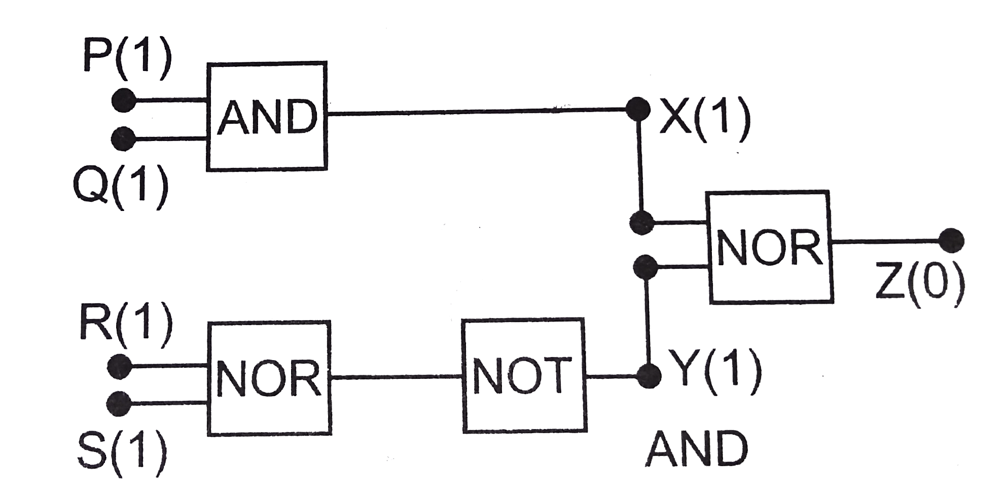
- The circuit diagram (see fig.) shows a 'logic combination' with the st...
Text Solution
|
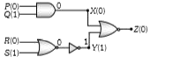
- The circuit diagram (see fig.) shows a 'logic combination' with the st...
Text Solution
|
- The diagram shows a logic network. If the inputs L,M and N are all at ...
Text Solution
|
- Logic gates X and Y have the truth tables shown below |(P,Q,R,P,R...
Text Solution
|
- Logic gates X and Y have the truth tables shown below {:(P,Q,R,P,...
Text Solution
|
- The output y, when all three inputs are first high and then low, will ...
Text Solution
|
- When the inputs of a two input logic gate are 0 and 0, the output is 1...
Text Solution
|
- In the given circuit P and Q from the inputs. The output Y is
Text Solution
|
- The circuit diagram shows a logic combination with the states of outpu...
Text Solution
|