A
B
C
D
Text Solution
Verified by Experts


Topper's Solved these Questions
JEE ADVANCED 2022
JEE ADVANCED PREVIOUS YEAR|Exercise PHYSICS (SECTION 3)|4 VideosJEE ADVANCED 2022
JEE ADVANCED PREVIOUS YEAR|Exercise PHYSICS (SECTION-1)|8 VideosJEE ADVANCED 2022
JEE ADVANCED PREVIOUS YEAR|Exercise PHYSICS (SECTION-3)|4 VideosJEE ADVANCED 2021
JEE ADVANCED PREVIOUS YEAR|Exercise QUESTION|38 VideosMOCK TEST 2022
JEE ADVANCED PREVIOUS YEAR|Exercise QUESTIONS|18 Videos
JEE ADVANCED PREVIOUS YEAR-JEE ADVANCED 2022-PHYSICS (SECTION 2)
- In the figure , the inner (shaded ) region .A represents a sphere of r...
Text Solution
|
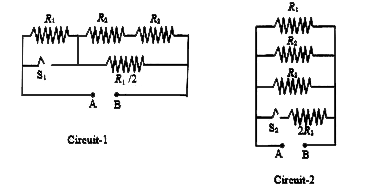
- In Circuit-1 and Circuit-2 shown in the figures R(1)=1 Omega ,R(2) = 2...
Text Solution
|
- A bubble has surface tension S. The ideal gas inside the bubble has ra...
Text Solution
|
- A disk of radius R with uniform positive charge density sigma is plac...
Text Solution
|
- A double slit setup is shown in the figure. One of the slits is in med...
Text Solution
|
- In the given P-V diagram, a monoatomic gas (gamma = 5/3) is is first c...
Text Solution
|