


Similar Questions
Explore conceptually related problems
Recommended Questions
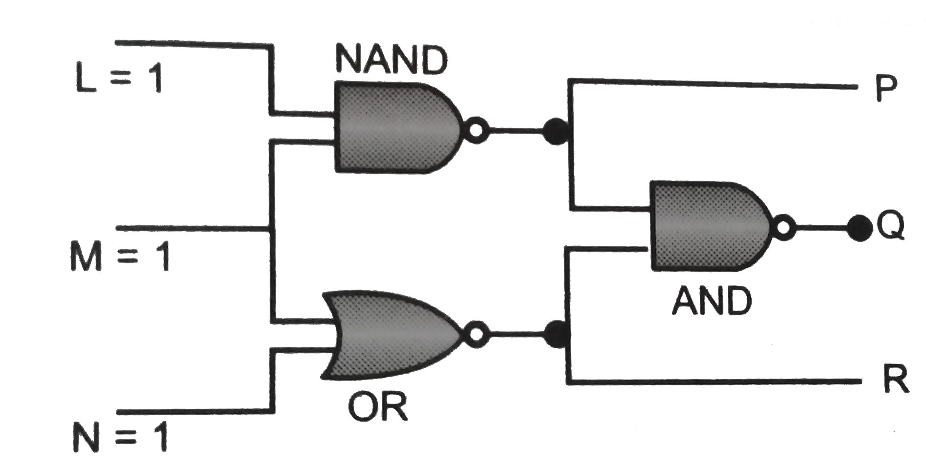
- The diagram shows a logic network. If the inputs L,M and N are al...
Text Solution
|
- The diagram shows a logic network. If the inputs L,M and N are all at ...
Text Solution
|
- The diagram shows a logic network. Which single gate is equivalent to ...
Text Solution
|
- p ^^ ( q ^^ r) is logically equivalent to
Text Solution
|
- जिस लॉजिक गेट के दोनों निवेशों ( inputs ) को केवल अवस्था 1 में रहने ...
Text Solution
|
- जिस लॉजिक गेट के दोनों निवेशों ( inputs ) को अवस्था 0 में रहने देने ...
Text Solution
|
- For given logic diagram, outupt F = 1, then inputs are
Text Solution
|
- P ^^ (q ^^ r) is logically equivalent to
Text Solution
|
- The circuit diagram shows a logic combination with the states of outpu...
Text Solution
|