


Similar Questions
Explore conceptually related problems
Recommended Questions
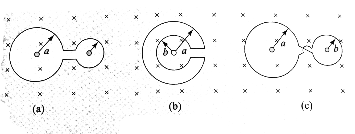
- Figure 3.15(a) shown two circular rings of radii a and b (a gt b) join...
Text Solution
|
- The resistances of three parts of a circular loop are as shown in Fig....
Text Solution
|
- Figure 3.15(a) shown two circular rings of radii a and b (a gt b) join...
Text Solution
|
- The magnetic field through a circular loop of wire 12 cm in radius and...
Text Solution
|
- The figure shows an infinitely long current wire out of the plane of t...
Text Solution
|
- shown in the figure is a small loop that is kept co-axially with the b...
Text Solution
|
- A circular loop placed in uniform B is transformed into elliptical loo...
Text Solution
|
- चित्र में प्रदर्शित लूप में फलकों A तथा B पर धुव्रता बताइए।
Text Solution
|
- चित्र में दर्शाए अनुसार R त्रिज्या का एक वृत्ताकार तार लूप (पाश) x-y त...
Text Solution
|