


Similar Questions
Explore conceptually related problems
Recommended Questions
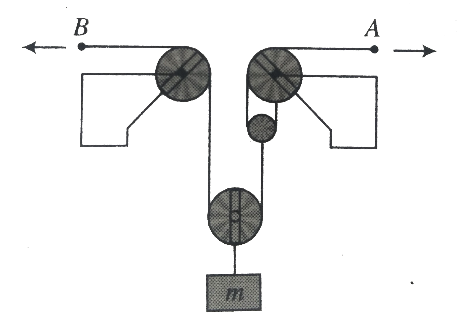
- For the pulley system shown in fig. each of the cables at A and B is g...
Text Solution
|
- System is shown in fig. and wedge is moving toward left with speed 2ms...
Text Solution
|
- If the string is inextensible, determine the velocity u of each block ...
Text Solution
|
- For the pulley system shown in fig. each of the cables at A and B is g...
Text Solution
|
- The velocity of point A on the rod is 2ms^(-1) (leftwards) at the inst...
Text Solution
|
- For the system shown in Fig. the string is light and pulley is frictio...
Text Solution
|
- A system is shown in the End B of string is moving upwards with sqrt3 ...
Text Solution
|
- A system of pulleys is used to lift a load of 1000 kg(wt). If the effi...
Text Solution
|
- Find out the velocity of block B in a pulley block system as shown in ...
Text Solution
|