


Similar Questions
Explore conceptually related problems
Recommended Questions
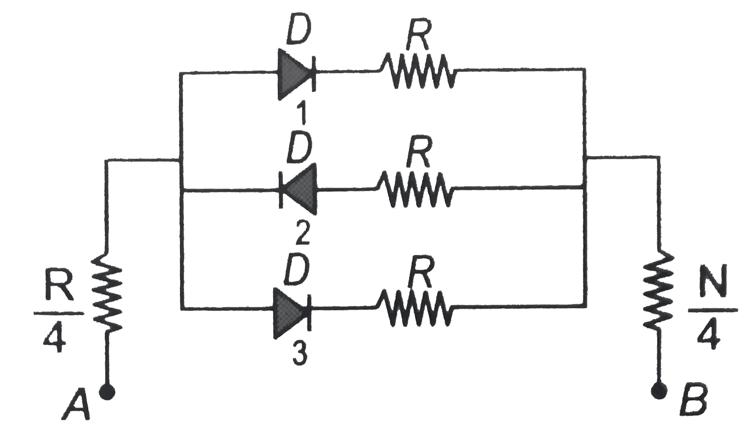
- In the following circuits PN-junction diodes D(1), D(2) and D(3) are i...
Text Solution
|
- If d1,d2,d3 are the diameters of three ex-circles of a triangle then ...
Text Solution
|
- Let d(1),d(2),d(3),......,d(k) be all the divisors of a positive integ...
Text Solution
|
- In the following circuits PN -junction diodes D(1), D(2) and D(3) are ...
Text Solution
|
- In the following circuit of PN junction diodes D(1),D(2) and D(3) are ...
Text Solution
|
- Considering the circuit and data given in the diagram, calculate the c...
Text Solution
|
- Two ideal junction diodes D(1),D(2) are connected as shown in the figu...
Text Solution
|
- Two ideal diodes D(1) and D(2) are connected with the battery of 5 vol...
Text Solution
|
- [" An alpha-particle is projected towards "],[" a Cu nucleus,an Au nuc...
Text Solution
|