


Similar Questions
Explore conceptually related problems
Recommended Questions
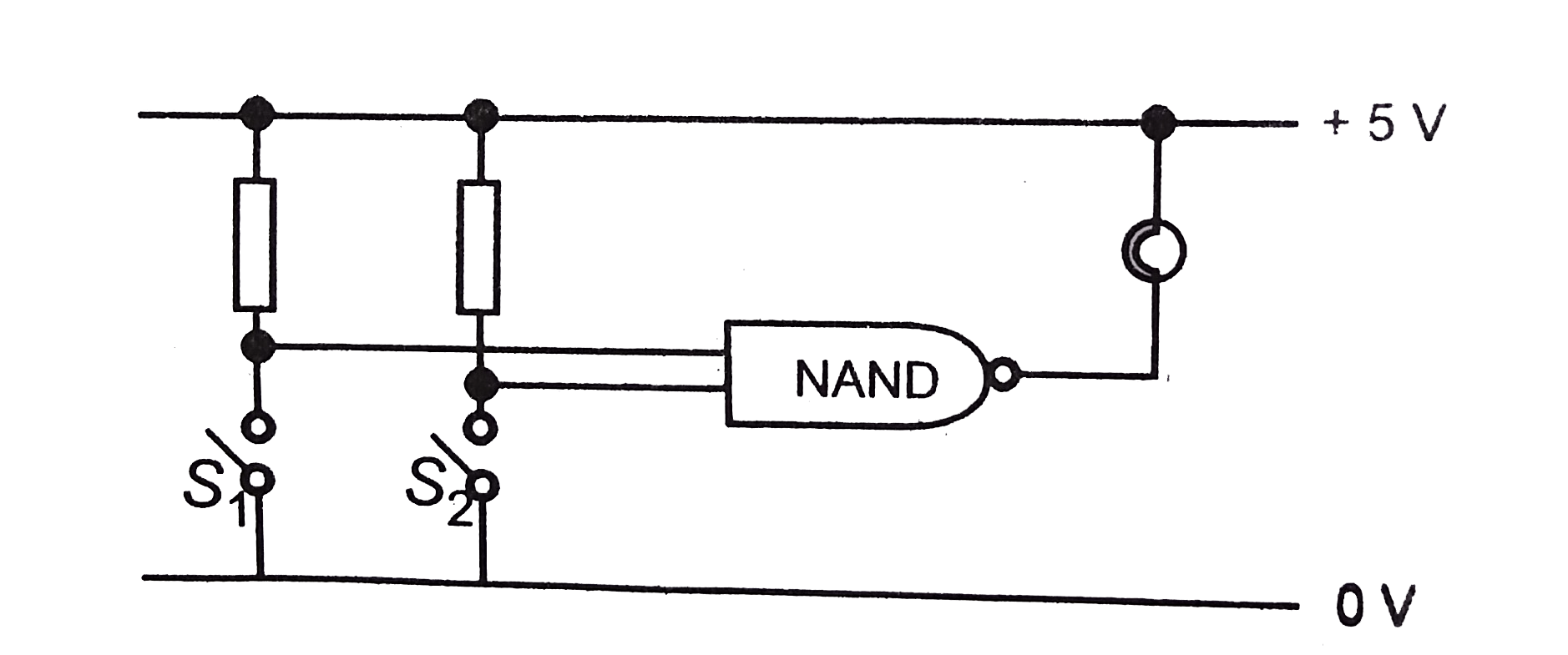
- Figure shows a circuit designed to control a lamp. For what positions ...
Text Solution
|
- In the circuit shown in the figure, if switches S(1) and S(2) have bee...
Text Solution
|
- In the circuit shown, when switch S(1) is closed and S(2) is open, the...
Text Solution
|
- Figure shows a circuit designed to control a lamp. For what positions ...
Text Solution
|
- In the given circuit, the initial charges on the capacitors are shown ...
Text Solution
|
- In the circuit shown, the capacitor is initially charged with a 12V ba...
Text Solution
|
- In the circuit shown, the capacitor initially charged with a 12V batte...
Text Solution
|
- Using the circuit given below, state which of the following statemet i...
Text Solution
|
- A circuit consists of three identical lamps connected to a battery as ...
Text Solution
|