Text Solution
Verified by Experts


HC VERMA-CAPACITORS-Exercises
- Three capacitors having capanctances 20muF, 30muF and 40muF are conne...
Text Solution
|
- Find the charges on the three capacitors connected to a bettery as sho...
Text Solution
|
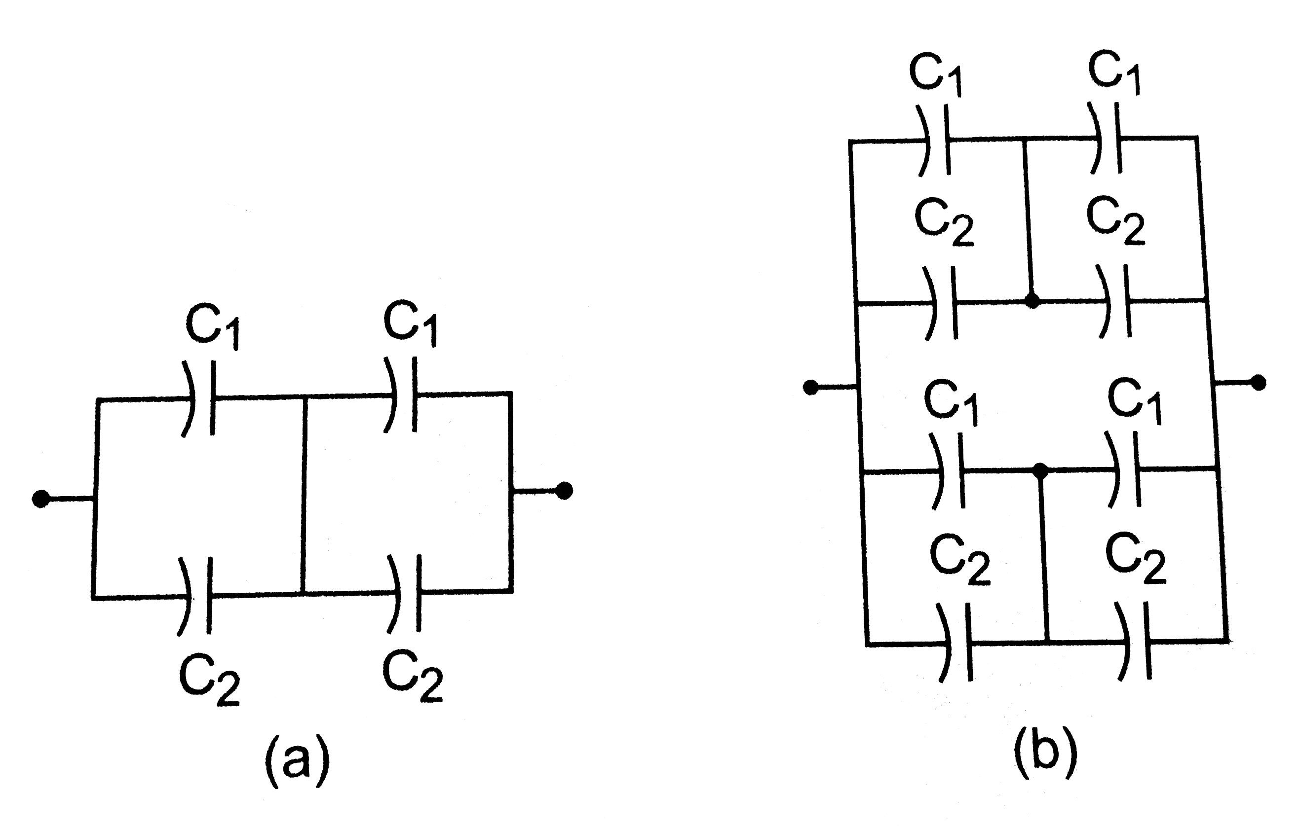
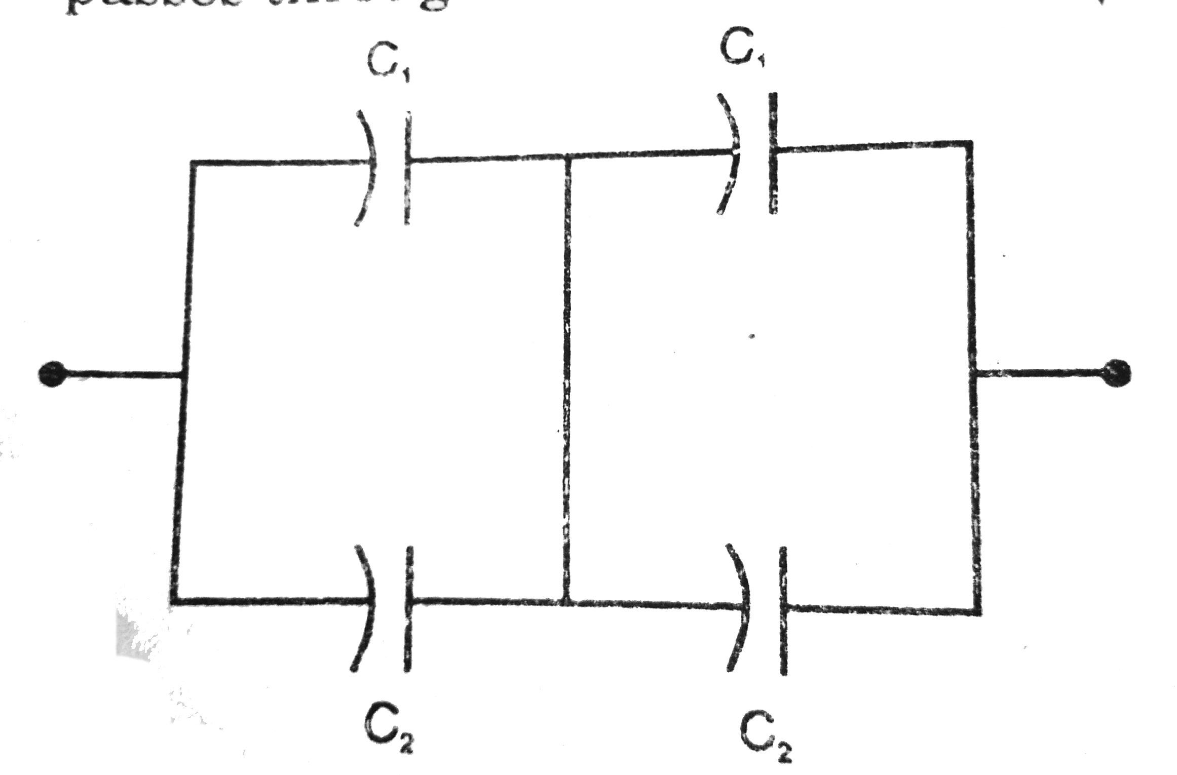
- Take C1=4.0mu F and C2=6.0mu F in figure. Calculate the equivalent cap...
Text Solution
|
- Find charge supplied by the battery in the arrangement shown in figur...
Text Solution
|
- The outer cyliunders of two cylindrical capacitors of capacitance 2.2 ...
Text Solution
|
- Two conducting spberes of radiiR1 and R2 are kept widely separated fro...
Text Solution
|
- Each of the capacitors shown n figure has a capacitance of 2 mu F . Fi...
Text Solution
|
- It is required to consttruct a 10 mu F capacitor which can be connect...
Text Solution
|
- Take the potential of the point B in figure to be zero . (a) Find the...
Text Solution
|
- Find the equivalent capacitance of the system shown in figure betwee...
Text Solution
|
- A capacitor is made of a flat plate of area A and B second plate havin...
Text Solution
|
- A cylindrical capacitor is constructed using two coaxial cylinders of ...
Text Solution
|
- A100 mu F capacitor is charged o a potential difference of 24 V. It is...
Text Solution
|
- Each capacitor shown in figure has a capacitance of 5.0n mu F , The e...
Text Solution
|
- Both the cacpacitors shown in figure are made ofsquare of edge a The ...
Text Solution
|
- The plate of a capacitor are 2.00cm apert . An electron -prodon pair i...
Text Solution
|
- Convince yourself that parts (a) ,(b) and (c ) of figure are identica...
Text Solution
|
- Find the potential difference Va -Vb between the points a and b shown...
Text Solution
|
- Find the equivalent capacitances of the combinations shown in figure ...
Text Solution
|
- Find the capacitance of the combination shown in figure between A and...
Text Solution
|