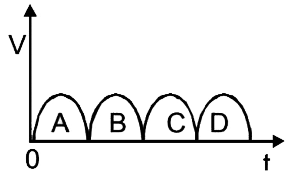
A full - wave rectifier circult along the out - put is shown in figure . The contribution (s) from the diode `1` is are .`
A
`C`
B
`A,C`
C
`B,D`
D
`A,B,C,D`
Text Solution
Verified by Experts
The correct Answer is:
B
As shown in the fig (i) during one half cycle the reversed biased and bence non conducting. `(# JMA_MP_C17_037_S01.png" width="80%"> During the ofter half cycle, diode (i) gets forward biased and is conducting . Thus diode (1) conduct in the ofter so the correct option is (b) (a and c)
SUNIL BATRA (41 YEARS IITJEE PHYSICS)|Exercise Comprehension Based Questions|2 Videos
MOVING CHARGES AND MAGNETISM
SUNIL BATRA (41 YEARS IITJEE PHYSICS)|Exercise MCQs(d )|1 Videos
Similar Questions
Explore conceptually related problems
A full wave rectifier circuit along with the output is shown in the following diagram. The contribution(s) from the diode (1) is (are) -
A full wave rectifier with the output is shown in fig. the contributions from the diode (2) are. .
A full wave rectifier circuit along with the input and output are shown in Fig. the concentrations from the diode I is (are)
In the output graph of a full rectifier shown , the contributions from the diode D_(2) correspond to
From the Zener diode circuit shown in figure, the current through the Zener diode is
in a sine wave ,postive of different particles at time t=0 is shown in figure. The equation for this wave if it is travelling along postive x -axis can beB
The rms value of input voltage in a full wave rectifier is 12 V determine the output voltage if a step up a transformer with ratio 1:2 is used
SUNIL BATRA (41 YEARS IITJEE PHYSICS)-MODERN PHYSICS-MCQ (One Correct Answer
 .`
.`