
Text Solution
Verified by Experts


Topper's Solved these Questions
Similar Questions
Explore conceptually related problems
DC PANDEY-CURRENT ELECTRICITY-Medical entrances gallery
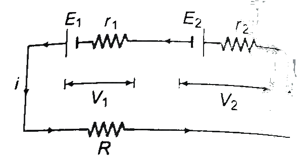
- In the circuit shown in figure E1=10 V, E2=4V, r1=r2=1Omega and R...
Text Solution
|
- A potentiometer wire is 100 cm long hand a constant potential differen...
Text Solution
|
- The charge flowing through a resistance R varies with time t as Q = at...
Text Solution
|
- The potential difference (V(A) - V(B)) between the point A and B in th...
Text Solution
|
- A filament bulb (500 W, 100 V) is to be used in a 230 V main supply. W...
Text Solution
|
- A potentiometer wire has length 4 m and resistance 8 Omega. The resist...
Text Solution
|
- A, B and C are voltmeters of resistances R, 1.5R and 3R respectively. ...
Text Solution
|
- A cross a metallic conductor of non-uniform cross-section, a constant ...
Text Solution
|
- Consider the diagram shown below. A Voltmeter of resistance 150 O...
Text Solution
|
- Each resistor shown in the figure has a resistance of 10 Omega and the...
Text Solution
|
- A 1 Omega resistance in series with an ammeter is balanced by 25 cm of...
Text Solution
|
- The range of voltmeter is 10 V and its internal resistance is 50 Omega...
Text Solution
|
- Identify the wrong statement.
Text Solution
|
- When the rate of flow of charge through a metallic condoctor of non-un...
Text Solution
|
- The resistance of a carbon resistor of colour code Red-Red Green Silve...
Text Solution
|
- The slope of the graph showing the variation of potential difference V...
Text Solution
|
- Two wires of the same dimensions but resistivities rho(1) and rho(2) a...
Text Solution
|
- A galvanometer of resistance 50 Omega is connected to a battery of 8 V...
Text Solution
|
- Choose the correct statement.
Text Solution
|
- A metal plate weighting 750g is to be electroplated wiwth 0.05% of it...
Text Solution
|
- A DC ammeter has resistance 0.1 Omega and its current ranges 0-100 A. ...
Text Solution
|