Text Solution
Verified by Experts
The correct Answer is:


Topper's Solved these Questions
CURRENT ELECTRICITY
DC PANDEY|Exercise Level 2 Single Correct|26 VideosCURRENT ELECTRICITY
DC PANDEY|Exercise Level 2 More Than One Correct|10 VideosCURRENT ELECTRICITY
DC PANDEY|Exercise OBJECTIVE_TYPE|1 VideosCOMMUNICATION SYSTEM
DC PANDEY|Exercise Subjective|11 VideosELECTROMAGNETIC INDUCTION
DC PANDEY|Exercise Medical entrances gallery|25 Videos
Similar Questions
Explore conceptually related problems
DC PANDEY-CURRENT ELECTRICITY-Level 1 Subjective
- The emf E and the internal resistance r of the battery shown in figure...
Text Solution
|
- Find the current in each branch of the cirucit shown in figure
Text Solution
|
- An electrical circuit is shown in figure. Calculate the potential diff...
Text Solution
|
- In the circuit shownin figure V1 and V2 are two voltmeter of resistanc...
Text Solution
|
- In figure circuit section AB absorbs energy at the rate of 5.0 W when ...
Text Solution
|
- The potential difference across the terminals of a battery is 8.4 V wh...
Text Solution
|
- A battery of emf 2.0 V and internal resistance 0.10 Omega is being cha...
Text Solution
|
- Find the currents in different resistors shown in figure
Text Solution
|
- A resistance box, a battery and a galvanometer of resistance G ohm are...
Text Solution
|
- Determine the resistance r if an ammeter shows a current of I = 5 A an...
Text Solution
|
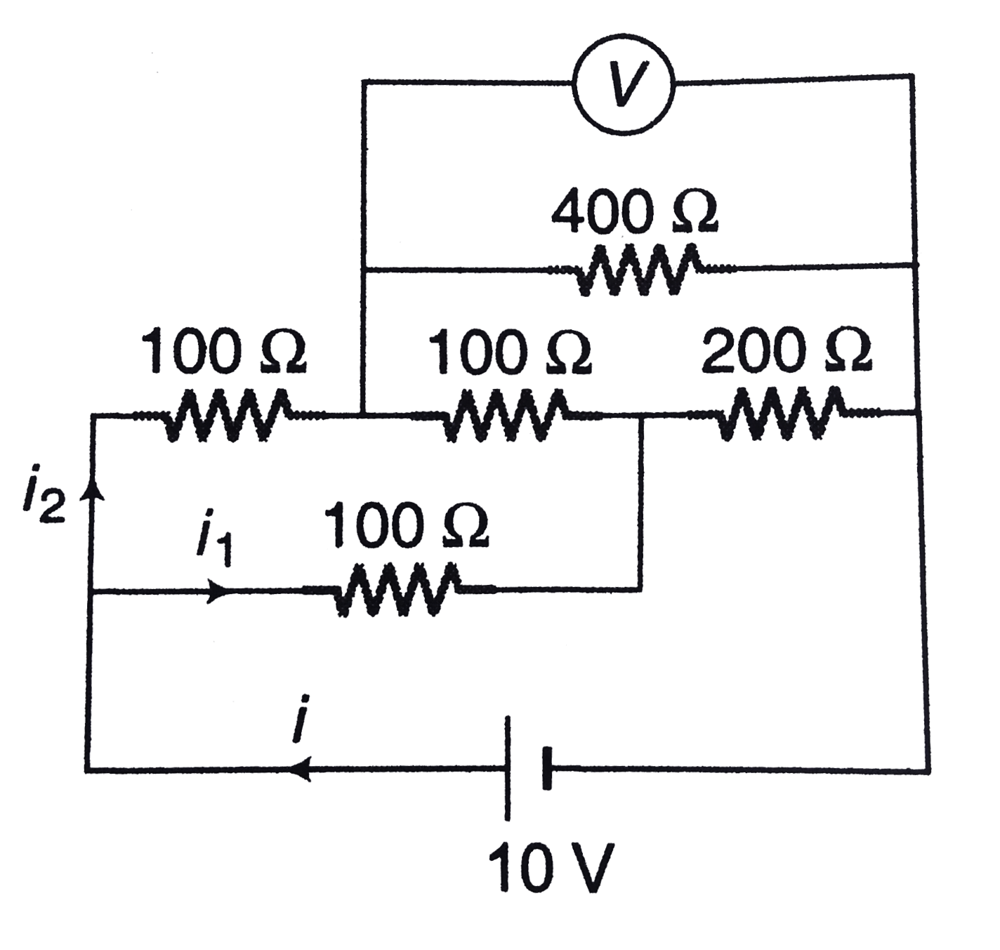
- In the circuit, a voltmeter reads 30 V when it is connected across 400...
Text Solution
|
- Resistance R1and R2, each 60 Omega, are connected in series. The point...
Text Solution
|
- A moving coil galvanometer of resistance 20 Omega gives a full scale d...
Text Solution
|
- A cell of emf 3.4 V and internal resistance 3 Omega is connected to an...
Text Solution
|
- (a) A voltmeter with resistance Rv is connected across the terminals o...
Text Solution
|
- An ammeter with resistance RA is connected in series with a resistor R...
Text Solution
|
- Each of three resistors in figure has a resistance of 2.4 Omega and ca...
Text Solution
|
- A storage battery with emf 2.6 V loaded with external resistance produ...
Text Solution
|
- In the circuit shown in figure E1=7V,E2=1 V,R1=2Omega, R2=2Omega and R...
Text Solution
|
- In the circuit shown in figure find a) the rate of conversion of ...
Text Solution
|