A
B
C
D
Text Solution
Verified by Experts
The correct Answer is:


Topper's Solved these Questions
CURRENT ELECTRICITY
DC PANDEY|Exercise Level 2 Comprehension Example Type|2 VideosCURRENT ELECTRICITY
DC PANDEY|Exercise Level 2 Subjective|13 VideosCURRENT ELECTRICITY
DC PANDEY|Exercise Level 2 Single Correct|26 VideosCOMMUNICATION SYSTEM
DC PANDEY|Exercise Subjective|11 VideosELECTROMAGNETIC INDUCTION
DC PANDEY|Exercise Medical entrances gallery|25 Videos
Similar Questions
Explore conceptually related problems
DC PANDEY-CURRENT ELECTRICITY-Level 2 More Than One Correct
- Two heaters designed for the same voltage V have different power ratin...
Text Solution
|
- Two cells of emf E1=6V and E2=5 are joined in parallel with same polar...
Text Solution
|
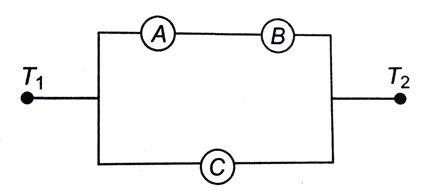
- Three ammeters A,B, and C of resistances RA,Rb and RC respectively are...
Text Solution
|
- Three voltmeters all having different resistance, are joined as shown....
Text Solution
|
- Two conductors made of the same material have lengths L and 2L but hav...
Text Solution
|
- In the figure shown, find the incorrect statement
Text Solution
|
- In the poteniometer experiement shown in figure, the null point length...
Text Solution
|
- In the circuit shown in figure, reading of ammeter will
Text Solution
|
- In the circuit shown in figure it is given that Vb-Va=2 volt. Choose t...
Text Solution
|
- Each resistance of the network shown in figure is r. Net resistance be...
Text Solution
|