Let us draw two figure and find the charge on both the capacitors before closing the switch and after closing the switch.

Refer fig a. when switch is open Both capacitors are in series. Hence, their equivalent capacitance is
`C_(eq)=(C_1C_2)/(C_1+C_2)((2)(3))/(2+3)=6/5muF`
therefore, charge on both capacitors will be same, Hence, using `q=CV` we get
`q=(30+60)(6/5)muC=108muC`
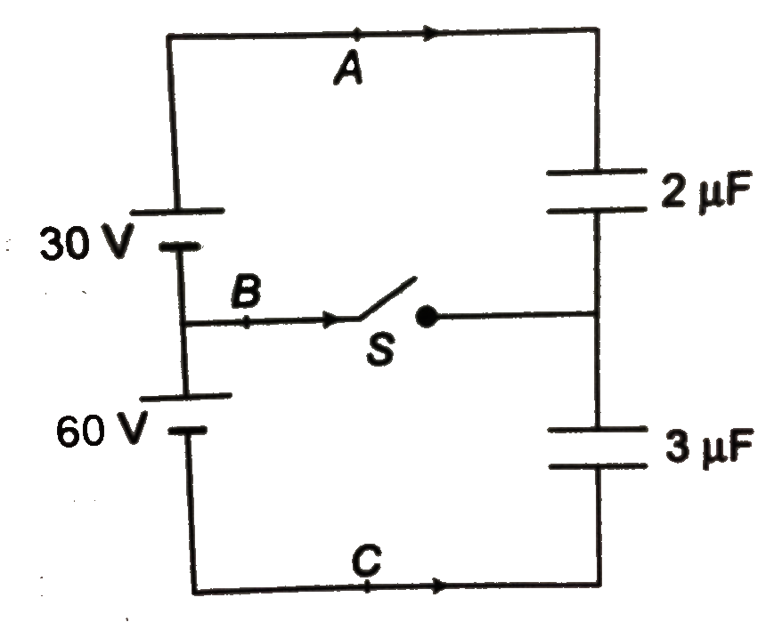
Refer fig b. when switch is closed Let `q_1` and `q_2` be the charges (`i n muC)` on two capacitors. Then applying second law in upper and lower loops, we have
`30-q_1/2=0` or `q_1=60muC`
`60-q_2/3=0` or `q_2=180muC`
Charges `q_1` and `q_2` can be calculated alternatively by seeing that upper plate of `2muF` capcior is connected with positive terminal of `30 V` battery. THereforwe, they are at the same potential. Similarly, thelower plate of this capacitor is at the same potential as that of the negative terminal of `30 V` battery. So, we can say that `PD` across `2muF` capacitor is also `30 V`.
`q_1=(C)(PD)=(2)(30)muC`
`=60muC`
Similarly `PD` across `3muF` capacitor is same as that between `60 V` battery. hence,
`q_2=(3)(60)muC`
`=180muC`
Now let `q_A` charge flows from `A` in the direction shown. This charge goes to the upper plate of `2muF` capacitor. initialy, it had charge `+q` and final charge on it is `+q_1` Hence
`q_1=q+q_A`
or `q_A=q_1-q=60-108`
`=-48muC`
Similarly charge `q_B` goes to the upper plate of `3muF` capacitor and lower plate of `2muF` capacitor. INitially both the plates had a chaerge `+q-q` or zero. And finally they have a charge `(q_2-q_1)`
Hence
`(q_2-q_1)=q_B+0`
`:. q_B=q_2-q_1=180-60`
`=120muC`
Charge `q_C` goes to the lower plate of `3muF` capacitor. Initially, it had a charge `-q` and finally `-q_2` Hence ltbr `-q_2=(-q)+q_C`
`q_C=q-q_2=108-180`
`=-72muC`
so, the charges will flow as shown below