Home
Class 12
PHYSICS
In the circuit shown in figure switch S ...

In the circuit shown in figure switch `S` is closed at time `t=0`. Find

a. Initial current at `t=0` and final current at `t=oo` in the loop.
b. total charge `q` flown from the switch.
c. Final charges on capacitors in steady state at time `t=oo`
d. Loss of energyduring resistribution of charges
e. Individual loss across `1Omega` and `2Omega` resistance.

Text Solution

Verified by Experts

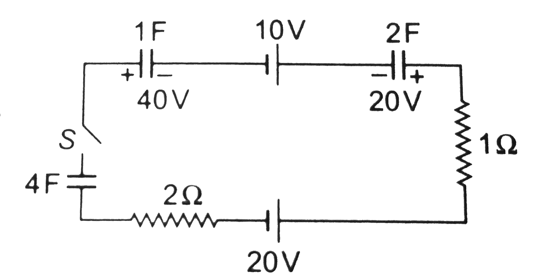
a. At `t=0` Three capacitors my be assumed like batteries of emf `40 V , 20V` and `0V`.ltbr. ` i=(Net emf)/(Total resistance)`
`=(40+20-10-20)/(1+2)`
`=10A` (anti clock)
At `t=oo` When charge redistribution is complete and loop is balanced by Kirchoff's second equation of potential current in the loop becomes zero, as insulator is filled between the capacitors.
b. Redistribution curren was anti clockwise. So, we can assume that `+q` charge rotates anti clockwise in the loop (between time` t=0` and `t=oo`) After this rotation of charges final charges on different capacitors are as shown below.

Applying loop equation in loop `abcda`,
`((40-q))/1+10+((40+q))/2-20+q/4=0`
Solving this equation we get `q=120/7`C
c. Final charges
`q_(1F)=40-q=40-120/7=160/7C`
`q_(2F)=40+q=40+120/7=400/7C`
`q_(4F)=q=120/7C`
d. Total loss of energy during redistribution
`SigmaU_i=1/2xx(1)(40)^2+1/2xx(2)(20)^2=1200J`
`SigmaU_=1/2xx((160/7)^2)/1+1/2xx((400/7)^2)/2+1/2xx((120/7)^2)/4`
`=1114.3J`
`/_\U=Sigma _f-SigmaU_i=-85.7J`
20 V battery will suply energy but `10 V` batter will consume energy. So,
Total energy supplied `=20xx120/7-10xx120/7=171.4J`
Total heat produced =Energy supplied `-/_\U`
`=171.4-(-85.7)=257.1J`
e. Resistors are in sereis. Hence,
`HpropH` or `H_1/H_2=R_1/R_2=(1Omega)/(2Omega)=1/2`
`H_1=(1/(1+2))(257.1_=85.7J`
`H_2=(2/(1+2))(257.1)=171.4J`
Promotional Banner

Topper's Solved these Questions

  • CAPACITORS

    DC PANDEY|Exercise Exercise|155 Videos
  • CAPACITORS

    DC PANDEY|Exercise OBJECTIVE_TYPE|1 Videos
  • ATOMS

    DC PANDEY|Exercise MEDICAL ENTRANCES GALLERY|42 Videos
  • COMMUNICATION SYSTEM

    DC PANDEY|Exercise Subjective|11 Videos

Similar Questions

Explore conceptually related problems

In the circuit shown in figure switch S is closed at time t=0 Current I from the battery at time t is given by

In the circuit shown in figure switch S is closed at time t=0 At what time current through 3Omega resistance and 1H inductor are equal?

In the circuit shown, switch S is closed at time t = 0 . Find the current through the inductor as a function of time t .

In the circuit shown in figure switch S is closed at time t=0 Potential difference across 3Omega resistance at time t is given by

In the circuit shown in figure switch S is closed at time t=0 . The charge which passes through the battery in one time constant is

For the circuit shown in figure below, At t = 0, switch is closed, the initial current through resistor and final charge on capacitor are

In the circuit shown in figure-3.240 switch S is closed at time t=0. find the current through different wires and charge stored on the capacitor at any time t.

In the circuit shown, the switch 'S' is closed at t = 0 . Then the current through the battery steady state reached is

In the circuit shown in figure L=10H, R=5Omega, E=15V. The switch S is closed at t=0 . At t=2s the current in the circuit is