Home
Class 12
PHYSICS
A circuit has section AB as shown in fig...

A circuit has section `AB` as shown in figure. The emf of the source equals `E=10V`, the capacitor capacitances are equal to `C_1 =1.0muF` and `C_2=2.0muF`, and the potential difference `V_A-V_B=5.0V`. Find the voltage across each capacitor.

Text Solution

Verified by Experts

The correct Answer is:
A


`q` shown in figure is in `muC`
Now` V_A-1/1+10-q/2=V_B`
or `V_A-V_B-(3q)/2-10=5`
`:. q=10muC`
Now, `V=q/C` across each capacitor.
Promotional Banner

Topper's Solved these Questions

  • CAPACITORS

    DC PANDEY|Exercise OBJECTIVE_TYPE|1 Videos
  • CAPACITORS

    DC PANDEY|Exercise OBJECTIVE_TYPE|1 Videos
  • ATOMS

    DC PANDEY|Exercise MEDICAL ENTRANCES GALLERY|42 Videos
  • COMMUNICATION SYSTEM

    DC PANDEY|Exercise Subjective|11 Videos

Similar Questions

Explore conceptually related problems

A circuit has a section Ab shown in fig. The emf of the source equals E = 10V , the capacitances are equal to C_(1) = 1.0 muF and C_(2) = 2.0 muF , and the potential difference varphi_(A) - varphi_(B) = 5.0 V . Find the voltage across each capacitor.

A circuit has section AB as shown in The emf of the cell is 10 V , and the capacitors have capacitances C_(1)=1 muF and C_(2)=2 muF . .

A circuit has a section AB as shown in the fig. With E =10V. C_1= 1.0muF, C_2= 2.0muF and the potential difference V_A–V_B= 5V. The voltage across C_1 is :

Find the potential difference between the points A and B . (a) If V_A - V_B = 5 V , find voltage across each capacitor.

In the circuit shown the capacitors are C_(1)=15muF, C_(2)=10muF and C_(3)=25 muF . Find the potential difference across each capacitor.

For section AB of a circuit shown in , C_(1)=1 muF, C_(2)=2 muF, E=10 V , and the potential difference V_(A)-V_(B)=-10 V . Charge on capacitor C_(1) is .

A circuit shown in the figure consists of a battery of emf 10V and two capacitance C_(1) and C_(2) of capacitances 1.0muF and 2.0muF respectively. The potential difference V_(A) - V_(B) is 5V

Two capacitors of capacitances 10muF and 20muF are connected in series across a potential difference of 100V. The potential difference across each capacitor is respectively

Three capacitors 3 muF, 6 muF and 6 muF are connected in series to source of 120 V. The potential difference in volt, across the 3 muF capacitor will be

Two capacitors 3muF and 6muF are connected in series across a potential difference of 120V . Then the potential difference across 3muF capacitor is:

DC PANDEY-CAPACITORS-Exercise
  1. The dielectric to be used in a parallel-plate capacitor has a dielectr...

    Text Solution

    |

  2. Two condensers are in parallel and the energy of the combination is 0....

    Text Solution

    |

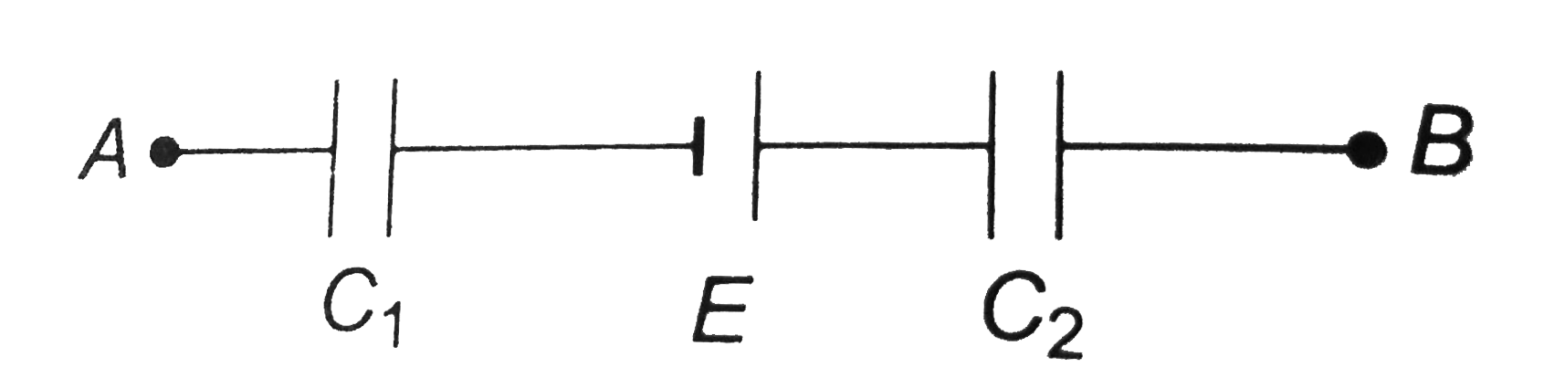
  3. A circuit has section AB as shown in figure. The emf of the source equ...

    Text Solution

    |

  4. Several 10 pF capacitors are given, each capable of withstanding 100 V...

    Text Solution

    |

  5. Two, capacitors A and B are connected in series across a 100 V supply ...

    Text Solution

    |

  6. A 10.0muF parallel-plate capacitor with circular plates is connected t...

    Text Solution

    |

  7. A 450 muF capacitor is charged to 295 V. Then, a wire is connected bet...

    Text Solution

    |

  8. The plates of a parallel-plate capacitor in vacuum are 5.00 mm apart a...

    Text Solution

    |

  9. Three capacitors having capacitances of 8.4 muF, 8.2muF and 4.21muF ar...

    Text Solution

    |

  10. Find the charges on 6muF and 4muF capacitors

    Text Solution

    |

  11. In figure C1=C5=8.4muF and C2=C3=C4=4.2muF.The applied potential is V(...

    Text Solution

    |

  12. Two condensers A and B each having slabs of dielectric constant K = 2 ...

    Text Solution

    |

  13. A capacitor of capacitance C1 = 1.0muF charged upto a voltage V = 110 ...

    Text Solution

    |

  14. In figure the battery has a potential difference of 20 V. Find (a...

    Text Solution

    |

  15. In figure, battery B supplies 12 V. Find the charge on each capacitor ...

    Text Solution

    |

  16. When switch S is thrown to the left in figure, the plates of capacitor...

    Text Solution

    |

  17. A parallel-plate capacitor has plates of area A and separation d and i...

    Text Solution

    |

  18. In the circuit shown in figure E1, 2E2=20V, R1=R2=10kOmega and C=1muF....

    Text Solution

    |

  19. (a) What is the potential of point a with respect to point b in figure...

    Text Solution

    |

  20. (a) What is the potential of point a with respect to point b in figure...

    Text Solution

    |