Home
Class 12
PHYSICS
In figure C1=C5=8.4muF and C2=C3=C4=4.2m...

In figure `C_1=C_5=8.4muF` and `C_2=C_3=C_4=4.2muF`.The applied potential is `V_(ab)=220V`

(a) What is the equivalent capacitance of the network between points `a` and `b`?
(b) Calculate the charge on each capacitor and the potential difference across each capacitor.

Text Solution

Verified by Experts

The correct Answer is:
A

a. Simple series and paralle grouping of capacitor.
b. `q_(n et)=C_(n et)V`
`=(2.5xx10^-6)(220)`
`=5.5xx10^-4C`
`C_1, C_5` and equivalent of other three capacitors are in series. Hence, charges across them are same

`q_("total")` will distribute between `C_2` and `C_34` in direct ratio of capacitance.
`:. q_2/q_34=4.2/2.1=2/1`
`:. q_2=2/3(5.5xx10^4)=3.7xx10^I-4C`
`q_32=1/3(5.5xx10^-4)=1.8xx10^-4C`
for finding PD across any capacitor use the equation
`C=q/V`
Promotional Banner

Topper's Solved these Questions

  • CAPACITORS

    DC PANDEY|Exercise OBJECTIVE_TYPE|1 Videos
  • CAPACITORS

    DC PANDEY|Exercise OBJECTIVE_TYPE|1 Videos
  • ATOMS

    DC PANDEY|Exercise MEDICAL ENTRANCES GALLERY|42 Videos
  • COMMUNICATION SYSTEM

    DC PANDEY|Exercise Subjective|11 Videos

Similar Questions

Explore conceptually related problems

In the circuit shown in figure find a. the equivalent capacitance b. the charge stored in each capacitor and c. the potential difference across each capacitor.

In the circuit shown in the figure, the potential difference across the 4.5 muF capacitor is

In the network shown in figure. C_(1)=C_(2)=C_(3)=C_(4)=10muF . Find th equivalent capacitance between the points A and B, what will be the charge on each capacitor?

In each capacitance C_(1) is 6.0 muF , and each capacitance C_(2) is 4.0 muF . . The equivalent capacitance of the netwok between ponts a and b is.

The equivalent capacitance of the combination between A and B in the given Fig. (i) Calculate capacitance of capacitor C . (ii) Calculate charge on each capacitor if a 12 V (iii) What will be the potential drop across each capacitor ?

In the circuit shown the capacitors are C_(1)=15muF, C_(2)=10muF and C_(3)=25 muF . Find the potential difference across each capacitor.

A 220 V AC supply is connected between points A and B. What will be potential difference across capacitor C ?

A capacitor or capacitance C_(1) is charge to a potential V and then connected in parallel to an uncharged capacitor of capacitance C_(2) . The fianl potential difference across each capacitor will be

Figure shows a network of seven capacitors. The charge on the 5muF capacitor si 10muC . The potential differenc between points A and C

DC PANDEY-CAPACITORS-Exercise
  1. Three capacitors having capacitances of 8.4 muF, 8.2muF and 4.21muF ar...

    Text Solution

    |

  2. Find the charges on 6muF and 4muF capacitors

    Text Solution

    |

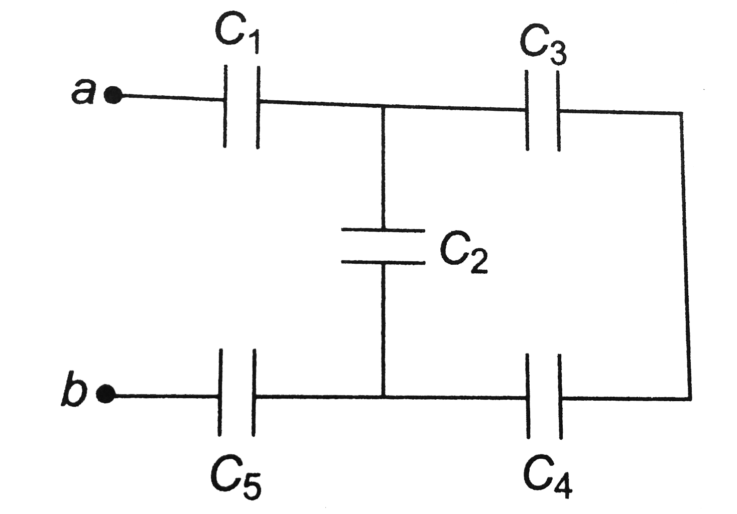
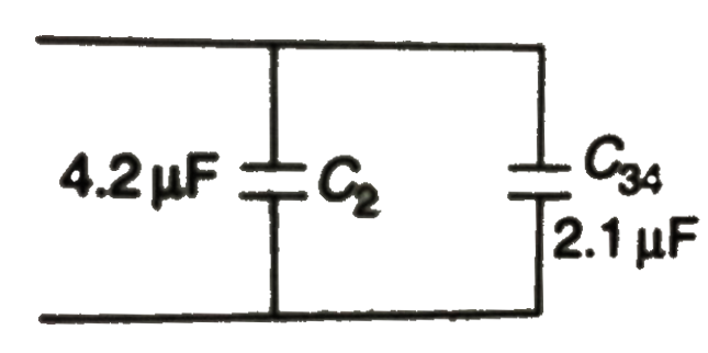
  3. In figure C1=C5=8.4muF and C2=C3=C4=4.2muF.The applied potential is V(...

    Text Solution

    |

  4. Two condensers A and B each having slabs of dielectric constant K = 2 ...

    Text Solution

    |

  5. A capacitor of capacitance C1 = 1.0muF charged upto a voltage V = 110 ...

    Text Solution

    |

  6. In figure the battery has a potential difference of 20 V. Find (a...

    Text Solution

    |

  7. In figure, battery B supplies 12 V. Find the charge on each capacitor ...

    Text Solution

    |

  8. When switch S is thrown to the left in figure, the plates of capacitor...

    Text Solution

    |

  9. A parallel-plate capacitor has plates of area A and separation d and i...

    Text Solution

    |

  10. In the circuit shown in figure E1, 2E2=20V, R1=R2=10kOmega and C=1muF....

    Text Solution

    |

  11. (a) What is the potential of point a with respect to point b in figure...

    Text Solution

    |

  12. (a) What is the potential of point a with respect to point b in figure...

    Text Solution

    |

  13. In the circuit shown in Figure, the battery is an ideal one, with emf ...

    Text Solution

    |

  14. Two very large thin conducting plates having same cross sectional are...

    Text Solution

    |

  15. The electric field on two sides of a thin sheet of charge is shown in ...

    Text Solution

    |

  16. In the circuit shown in figure, the capacitors are initially uncharged...

    Text Solution

    |

  17. A graph between current and time during charging of a capacitor by a b...

    Text Solution

    |

  18. A capacitor of capacitance C is charge by a battery of emf E and inter...

    Text Solution

    |

  19. For the circuit shown in the figure determine the charge on capacitor ...

    Text Solution

    |

  20. For the circuit shown in the figure, find the charge stored on capacit...

    Text Solution

    |