Home
Class 12
PHYSICS
In the circuit shown in Figure, the batt...

In the circuit shown in Figure, the battery is an ideal one, with emf V. The capacitor is initially uncharged. The switch S is closed at time t = 0 .
(a) Find the charge Q on the capacitor at time t.
(b) Find the current in AB at time t. What is its limiting value as `t rarr oo`:
.

Text Solution

Verified by Experts

The correct Answer is:
B, C

a. In steady state,
`V_C=V/2`
`:. ` Steady state charges,
`q_0=CV_C=(CV)/2`
For equivalent value of `tau_C`: we short circuit the battery and find the value of `R_(net)` across capacitors and then

`R_(net)=(3R)/2`
`:. tau_C=CR_(net)=(3RC)/2`
`Now, q=q_0(1-e^(-t/tau_C))`
b. At `t=0` capacitor offers zero resistance
`R_(net)=(3R)/2`
`:. i=V/(3R/2)=(2V)/(3R)`
`i_C=i_(AB)=1/2=V/(3R)`
`At t=oo` capacitor offers infinite resistance. So, `i_C=0`
`:. i_(battery)=i_(AB)=V/(2R)`
Now current through `AB` increases exponentially from `V/(3R)to V/(2R)` with same time constant.
`(i-t)` graph is as shown below.

(i-t) equation corresponding to this graph is
`i=V/(3R)+V/(6R) (1-e^(-t/tau_C))`
Promotional Banner

Topper's Solved these Questions

  • CAPACITORS

    DC PANDEY|Exercise OBJECTIVE_TYPE|1 Videos
  • CAPACITORS

    DC PANDEY|Exercise OBJECTIVE_TYPE|1 Videos
  • ATOMS

    DC PANDEY|Exercise MEDICAL ENTRANCES GALLERY|42 Videos
  • COMMUNICATION SYSTEM

    DC PANDEY|Exercise Subjective|11 Videos

Similar Questions

Explore conceptually related problems

In the circuit shown in figure-3.244, the battery is an ideal one with emf V. The capacitor is initially uncharged. The switch S is closed at time t=0. (a) Find the charge Q on the capacitor at time l (b) Find the current in branch AB at time just after closing the switch.

In the circnit shown, capacitor is initially uncharged till the switch is turned on at time t= 0 . Then

In the circuit shown, the capacitor C_1 is initially charged with charge q_0 . The switch S is closed at time t = 0 . The charge on C_2 after time t is

In the circuit shown, the capacitor is initially uncharged. The switch S is closed at t = 0. Time after which voltage across capacitor and resistor are equal is:

The switch S in the circuit diagram is closed at t = 0. The charge on capacitors at any time is

Switch S is cloesd in the circuit at time t = 0 . Find the current through the capacitor and the inductor at any time t

The switch shown in figure is closed at t=0 find the charge throuh battery till time t=(L)/(R)

The switch shown n the figure is closed at t=0 . The charge on the capacitor as a function of time is given by

The switch in figure is closed at time t = 0 . Find the current in the inductor and the current through the switch as functions of time thereafter.

DC PANDEY-CAPACITORS-Exercise
  1. (a) What is the potential of point a with respect to point b in figure...

    Text Solution

    |

  2. (a) What is the potential of point a with respect to point b in figure...

    Text Solution

    |

  3. In the circuit shown in Figure, the battery is an ideal one, with emf ...

    Text Solution

    |

  4. Two very large thin conducting plates having same cross sectional are...

    Text Solution

    |

  5. The electric field on two sides of a thin sheet of charge is shown in ...

    Text Solution

    |

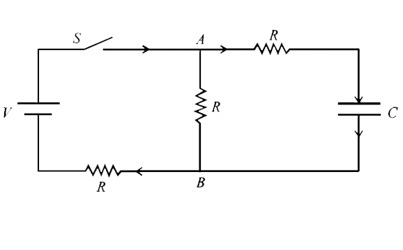
  6. In the circuit shown in figure, the capacitors are initially uncharged...

    Text Solution

    |

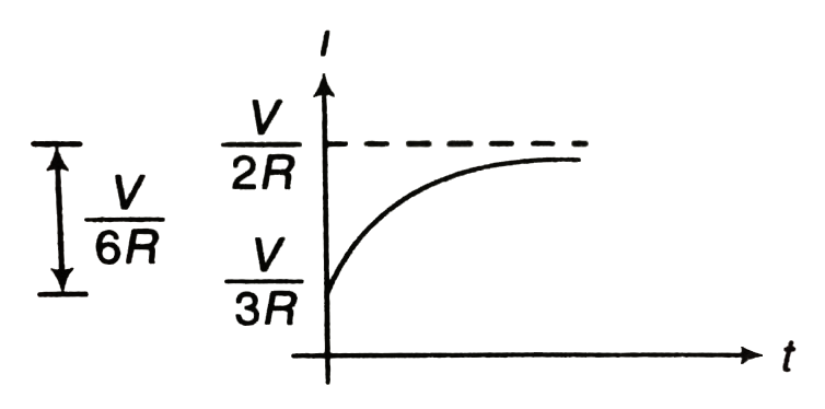
  7. A graph between current and time during charging of a capacitor by a b...

    Text Solution

    |

  8. A capacitor of capacitance C is charge by a battery of emf E and inter...

    Text Solution

    |

  9. For the circuit shown in the figure determine the charge on capacitor ...

    Text Solution

    |

  10. For the circuit shown in the figure, find the charge stored on capacit...

    Text Solution

    |

  11. Two similar parallel plate capacitors each of capaciti C0 are connecte...

    Text Solution

    |

  12. The switch shown n the figure is closed at t=0. The charge on the cap...

    Text Solution

    |

  13. A 2muF capacitor C1 is charge to a voltage 100 V and a 4muF capacitor ...

    Text Solution

    |

  14. The figure shows a graph of the current in a charging circuit of a cap...

    Text Solution

    |

  15. Four capacitors are connected inseries a battery of emf 10 V as shown ...

    Text Solution

    |

  16. A capacitor of capacity C is charged to a potential difference V and a...

    Text Solution

    |

  17. A capacitor of capacitance 2muF is charged to a potential difference o...

    Text Solution

    |

  18. In the circuit shown in figure switch S is thrown to position 1 at t=0...

    Text Solution

    |

  19. The flow of charge through switch S if it is closed is

    Text Solution

    |

  20. Consider the arrangement of three plates X,Y and Z each of the area A ...

    Text Solution

    |