Home
Class 12
PHYSICS
Four capacitors are connected inseries a...

Four capacitors are connected inseries a battery of emf `10 V` as shown in the figure. The point `P` is earthed. The potential of point `A` is equal in magnitude to potetial of points `B` but opposite in sign is

A

`C_1+C_2+C_3=C_4`

B

`1/C_1+1/C_2+1/C_3=1/C_4`

C

`(C_1C_2C_3)/(C_1^2+C_2^2+C_3^2)=C_4`

D

its is never possible

Text Solution

Verified by Experts

The correct Answer is:
B

Net capacitance between points `A` and `P` will be equal to the net capacitance between points `P` and `B`.
Promotional Banner

Topper's Solved these Questions

  • CAPACITORS

    DC PANDEY|Exercise OBJECTIVE_TYPE|1 Videos
  • CAPACITORS

    DC PANDEY|Exercise OBJECTIVE_TYPE|1 Videos
  • ATOMS

    DC PANDEY|Exercise MEDICAL ENTRANCES GALLERY|42 Videos
  • COMMUNICATION SYSTEM

    DC PANDEY|Exercise Subjective|11 Videos

Similar Questions

Explore conceptually related problems

Four identical capacitors are connected in series with a 10 V battery as shown in the figure. The point N is earthed. The potentials of points A and B are

Five capacitors are connected in series as shown in figure with a battery of emf 20V and the point B is earthed. The potential of point A is

In the circuit shown if point O is earthed, the potential of point X is equal to

In the circuit shown, the point B is earthed. The potential at the point 'A' is

Four capacitors of equal cpacitances are connected in series with a battery of 10 V, as shown in figure. The middle point B is connected to the earth. What will be the potentials of the points A and C?

As shown in figure, if the point C is earthed and the point A is given a potential of 2000 V, then the potential at point B will be :

Four capacitors are connected in a circuit as shown in the figure. The effective capacitance in muF between points A and B will be

Four capacitors and two batteries are connected as shown in the figure. The potential difference between the points a and b is:

Five capacitors are connected across a battery of 5V as shown in figure (o). Calculate the potential difference across the plates of the 5muF capacitor.

DC PANDEY-CAPACITORS-Exercise
  1. A 2muF capacitor C1 is charge to a voltage 100 V and a 4muF capacitor ...

    Text Solution

    |

  2. The figure shows a graph of the current in a charging circuit of a cap...

    Text Solution

    |

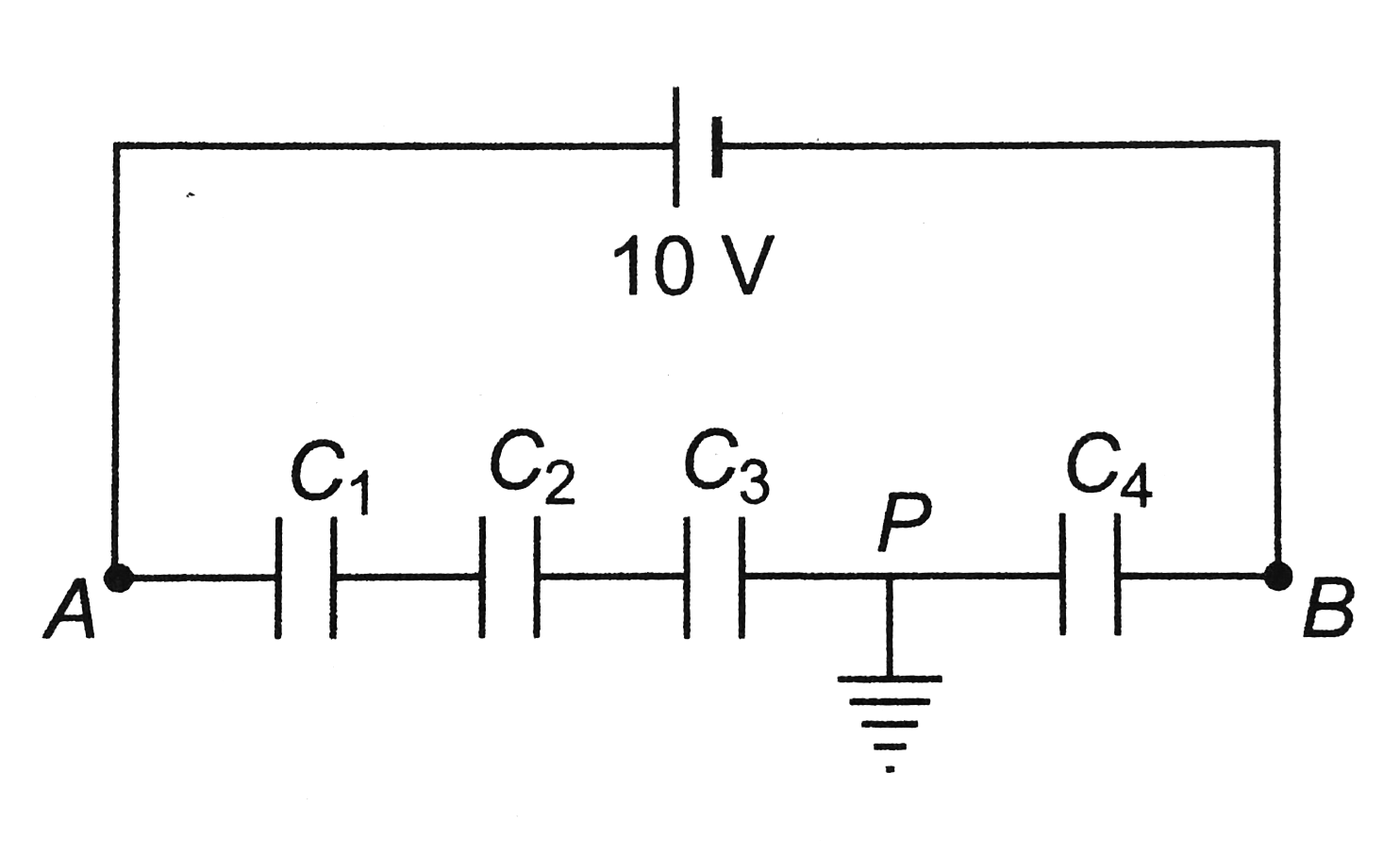
  3. Four capacitors are connected inseries a battery of emf 10 V as shown ...

    Text Solution

    |

  4. A capacitor of capacity C is charged to a potential difference V and a...

    Text Solution

    |

  5. A capacitor of capacitance 2muF is charged to a potential difference o...

    Text Solution

    |

  6. In the circuit shown in figure switch S is thrown to position 1 at t=0...

    Text Solution

    |

  7. The flow of charge through switch S if it is closed is

    Text Solution

    |

  8. Consider the arrangement of three plates X,Y and Z each of the area A ...

    Text Solution

    |

  9. Consider a capacitor charging circuit. Let Q1 be the charge given to t...

    Text Solution

    |

  10. The current in 1Omega resistance and charge stored in the capacitor ar...

    Text Solution

    |

  11. A capacitor C is connected to two equal resistances as shown in the fi...

    Text Solution

    |

  12. Two capacitors C1=1muF and C2=3muF each are charged to a potential dif...

    Text Solution

    |

  13. Four capacitors are connected as shown in figuere to a 30 V battery. T...

    Text Solution

    |

  14. Three uncharged capacitors of capacitance C1,C2 and C3 are connected t...

    Text Solution

    |

  15. In the circuit shown in figure potential difference between the points...

    Text Solution

    |

  16. Two cellls, two resistance and two capacitors are connected as shown i...

    Text Solution

    |

  17. In the circuit shown in figure, the capacitor is charged with a cell o...

    Text Solution

    |

  18. The potential difference between points a and b of circuits shown in f...

    Text Solution

    |

  19. A capacitors C1 is charged to a potential V and connected to another c...

    Text Solution

    |

  20. In the circuit diagram the current through the battery immediately aft...

    Text Solution

    |