Text Solution
Verified by Experts
The correct Answer is:


Topper's Solved these Questions
Similar Questions
Explore conceptually related problems
DC PANDEY-CAPACITORS-Exercise
- In the given circuit diagram, find the charges which flow through dire...
Text Solution
|
- Two capacitors A and B with capacities 3muF and 2muF are charged to a ...
Text Solution
|
- The capactor C1 in the figure initially carries a charge q0. When the ...
Text Solution
|
- A leaky parallel plate capacitor is filled completely with a material ...
Text Solution
|
- A parallel plate vacuum capacitor with plate area A and separation x h...
Text Solution
|
- A spherical capacitor has the inner sphere of radius 2 cm and the oute...
Text Solution
|
- Calculate the charge on each capacitor and the potential difference ac...
Text Solution
|
- In the shown network, find the charges on capacitors of capacitances 5...
Text Solution
|
- In the circuit shown, E = 18 kV, C = 10 muF,R1 = 4 MOmega, R2 = 6 MOme...
Text Solution
|
- The charge on the capacitor is initially zero. Find the charge on the ...
Text Solution
|
- The capacitors are initially uncharged. In a certain time the capacito...
Text Solution
|
- A capacitor of capacitance C has potential difference E/2 and another ...
Text Solution
|
- The capacitor shown in figure has been charged to a potential differen...
Text Solution
|
- The switch S is closed at t=0 . the capacitor C is uncharged but C0 ha...
Text Solution
|
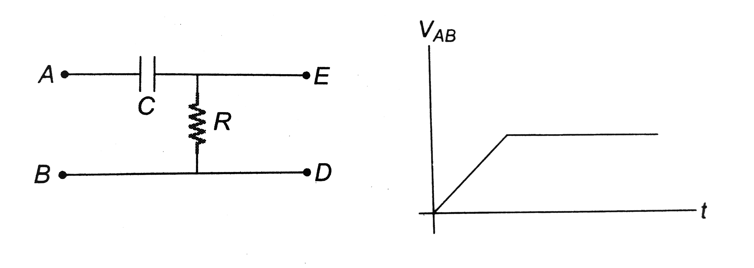
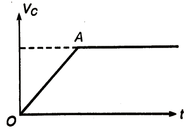
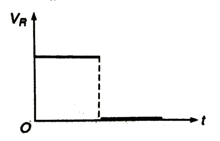
- A time varying voltage is applied to the clamps A and B such that volt...
Text Solution
|
- In the above problem if given graph is between V(AB) and time. Then pl...
Text Solution
|
- Initially, the switch is in position 1 for a long time. At t = 0, the ...
Text Solution
|
- For the arrangement shown in the figure, the switch is closed at t = 0...
Text Solution
|
- In the given circuit the switch ils closed in the positin 1 at t=0 and...
Text Solution
|
- A charged capacitor C1 is discharged through a resistance R by putting...
Text Solution
|