A
B
C
D
Text Solution
Verified by Experts
The correct Answer is:


Topper's Solved these Questions
ELECTROMAGNETIC INDUCTION
DC PANDEY|Exercise Objective Questions|3 VideosELECTROMAGNETIC INDUCTION
DC PANDEY|Exercise Level 1 Subjective|21 VideosELECTROMAGNETIC INDUCTION
DC PANDEY|Exercise Level 1 Assertion And Reason|10 VideosCURRENT ELECTRICITY
DC PANDEY|Exercise Medical entrances gallery|97 VideosELECTROMAGNETIC WAVES
DC PANDEY|Exercise Sec C|22 Videos
Similar Questions
Explore conceptually related problems
DC PANDEY-ELECTROMAGNETIC INDUCTION-Level 1 Objective
- The armature of a DC motor has 20Omega resistance. It draws a current ...
Text Solution
|
- In a transformer the output current and voltage are respectively 4 A a...
Text Solution
|
- When a loop moves towards a stationary magnet with speed v, the induce...
Text Solution
|
- A short magnet is allowed to fall from rest along the axis of a horizo...
Text Solution
|
- In figure, if the current i decreases at a rate alpha then VA-VB is
Text Solution
|
- A coil has an inductance of 50 m H and a resistance of 0.3Omega. If a ...
Text Solution
|
- A constant voltage is applied to a series R-L circuit by closing the s...
Text Solution
|
- A coil of area 10cm^2 and 10 turns is in magnetic field directed perpe...
Text Solution
|
- In figure final value of current in 10Omega resistor, when plug of key...
Text Solution
|
- A circuit consists of a circular loop of radius R kept in the plane of...
Text Solution
|
- A flat circular coil of n turns, area A and resitance R is placed in a...
Text Solution
|
- A small circular loop is suspended from an insulating thread. Another ...
Text Solution
|
- In the circuit shown in figure L=10H, R=5Omega, E=15V. The switch S is...
Text Solution
|
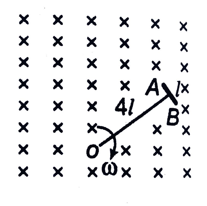
- In the figure shown a T-shaped conductor moves with constant angular v...
Text Solution
|
- A conducting rod of length l falls verticaly under gravity in a region...
Text Solution
|
- A semi circular conducting ring acb of radius R moves with constant sp...
Text Solution
|
- The ring B is coaxial with a solenoid A as shown in figure. As the swi...
Text Solution
|
- If the instantaneous magnetic flux and induced emf produced in a coil ...
Text Solution
|
- The figure shows a conducting ring of radius R. A uniform steady magne...
Text Solution
|
- A metallic rod of length l is hinged at the point M and is rotating ab...
Text Solution
|