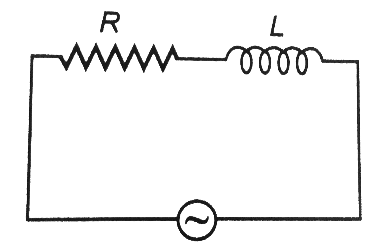
A
B
C
D
Text Solution
Verified by Experts
The correct Answer is:
Topper's Solved these Questions
Similar Questions
Explore conceptually related problems
DC PANDEY-ALTERNATING CURRENT-Level- 2 Single Correct
- A capacitor and resistor are connected with an AC source as shown in f...
Text Solution
|
- A circuit contains resistance R and an inductance L in series. An alte...
Text Solution
|
- In the circuit shown in figure the AC source gives a voltage V=20cos(2...
Text Solution
|
- A signal generator supplies a sine wave of 200V, 5kHz to the circuit s...
Text Solution
|
- A complex current wave is given by i=95+5sin100omegat)A. Its given val...
Text Solution
|
- An Ac voltage V=V0 sin 100t is applied to the circuit, the phase diffe...
Text Solution
|
- In series L-C-R circuit, voltage drop across resistance is 8V, across ...
Text Solution
|
- Consider in L-C-R circuit as shown in figureure with an AC source of p...
Text Solution
|
- The adjoining figure shows an AC circuit with resistance R, inductance...
Text Solution
|
- When an alternating voltage of 220 V is applied across a device P, a c...
Text Solution
|
- In a parallel L-C-R circuit as shown in figureure if IR,IL,IC and I re...
Text Solution
|
- In a series L-C-R circuit, currenrt in the circuit is 11A when the app...
Text Solution
|
- In the circuit shown in figureure, the power consumed is .
Text Solution
|
- In a series L-C circuit, the applied voltage is V0. if omega is very l...
Text Solution
|
- A coil a capacitor and an AC source of rms voltage 24 V are connected ...
Text Solution
|
- In a series C-R circuit shown in figureure, the applied voltage is 10 ...
Text Solution
|
- An AC voltage source described by V=10cos(pi/2)t is connected to a 1mu...
Text Solution
|
- An AC voltage source V=V0siomegatis connected across resistance R and ...
Text Solution
|
 .
.