Home
Class 12
PHYSICS
Only switch S1 closed in fig. a. what ...

Only switch `S_1` closed in fig.
a. what is the steady-state reading of the voltmeter?
b. What is the charge on the `3muF` capacitor?
c. How much power does the 12V battery supply in the steady state after all the switches are closed?
d. What is the charge on `2muF` capacitor?

Text Solution

Verified by Experts

a. As explained earliar that a capacitor is an open cirucit to DC
in steady state. The effective circuit through which current
will pass initially after closing switch `S_1` is shown is figure.
When steady state is reached, the capacitor will not allow
current. Thus, there is no current from battery. Reading of
voltmeter is zero.
b. Without current the resistor
act as conducting wires.
Hence, potentia difference
across capacitor is 12V. Charge on capacitor, `3muF,` is
`Q = (3xx2)muC = 36muC`

c. When all the switches are
closed, the branch contatining
capacitor will not allow
current after steady state is reached. The equivalent circuit
from point of view of current is redrawn as in figure.

Let the current in the single loop circuit be I. we begin at
left lower corner and traverse the circuit anticlockwise while
applying KVL. We get `-20 I +20-10 I - 12 = 0`
`I = (4)/(15)A`
Power received by 12 V battery is `P = VI = 12xx(4)/(15) = (16)/(5)W`
d. `V_c - 10 I - 12 = V_d`
or `V_c - V_d = (44)/(3)V or Q =CV = (88)/(3)muC`
Promotional Banner

Topper's Solved these Questions

  • ELECTRIC CURRENT AND CIRCUIT

    CENGAGE PHYSICS|Exercise Single Correct|72 Videos
  • ELECTRIC CURRENT AND CIRCUIT

    CENGAGE PHYSICS|Exercise Multiple Correct|16 Videos
  • ELECTRIC CURRENT AND CIRCUIT

    CENGAGE PHYSICS|Exercise Exercise 5.2|50 Videos
  • ELECTRIC CURRENT & CIRCUITS

    CENGAGE PHYSICS|Exercise Kirchhoff s law and simple circuits|15 Videos
  • ELECTRIC FLUX AND GAUSS LAW

    CENGAGE PHYSICS|Exercise MCQ s|38 Videos

Similar Questions

Explore conceptually related problems

In steady state, find the charge on 3muF capacitor in muC

Find power produced in 5 Omega resistance in steady state after closing the switch S :

Figure shows five capacitors connected across a 12V power supply. What is the charge on the 2muF capacitor ?

(a)Find the current I supplied by the battery in the network shown in figure in steady state. (b)find the charge on the capacitor.

Find the ratio of charges on 5muF and 10muF capacitor when circuit is in steady state. All the batteries are ideal.

In the given circuit, a charge of +80muC is given to the upper plate of the 4muF capacitor. Then in the steady state, the charge on the upper plate of the 3muF capacitor is

In the circuit shown in figure, the capacitor is charged with a cell of 5V .If the switch is closed at t=0 , then at t=12s , charge on the capacitor is

The two capacitors in the circuit shown in figure are initially uncharged and then connected as shown and switch is closed. What is the potential difference across 3muF capacitor?

CENGAGE PHYSICS-ELECTRIC CURRENT AND CIRCUIT-Subjective
  1. The circuit shown in fig 5.223 is in steady state. find the charges ...

    Text Solution

    |

  2. Consider an infinita ladder of network shown In fig 5.223A voltage is ...

    Text Solution

    |

  3. For a cicuit shown in fing 5.235 swhitch S1 is closed at t= 0, then at...

    Text Solution

    |

  4. Find the potential difference between the plates of the capactior C in...

    Text Solution

    |

  5. Analyze the given circuit in the steady state condition. Charge on the...

    Text Solution

    |

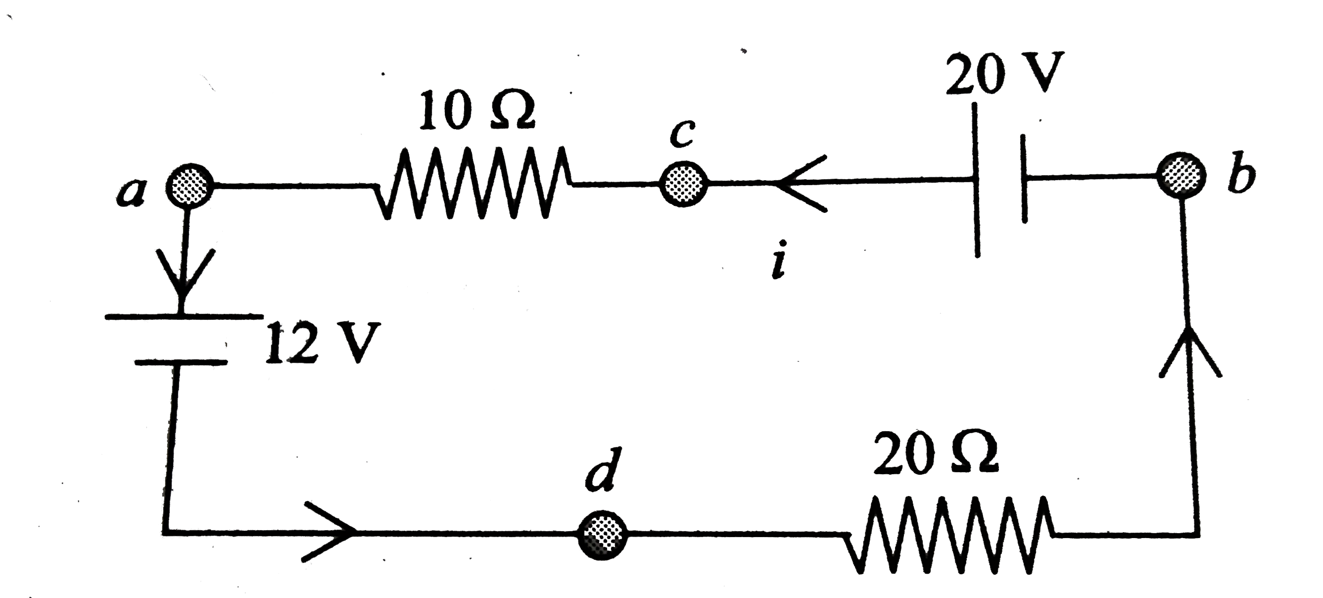
  6. (a) What is the potential of point a with respect to point b in figure...

    Text Solution

    |

  7. In the cicuit shown in fig. C is a parallel plate air capacitor having...

    Text Solution

    |

  8. The circuit shown in fig. Is in steady state. i. Find the energy...

    Text Solution

    |

  9. The given R-C circuit has two swithes S1 and S2 Swithc S2 is clsoed a...

    Text Solution

    |

  10. For the circuit arrangement shown in fig. a. Find the potentail d...

    Text Solution

    |

  11. The plates of a capacitor of capacitance C are given the charges Q1 an...

    Text Solution

    |

  12. Consider a parallel pate capacitor of capactance C with partially cond...

    Text Solution

    |

  13. The switch S is closed aty t = 0. the capacitor C is uncharged but C0 ...

    Text Solution

    |

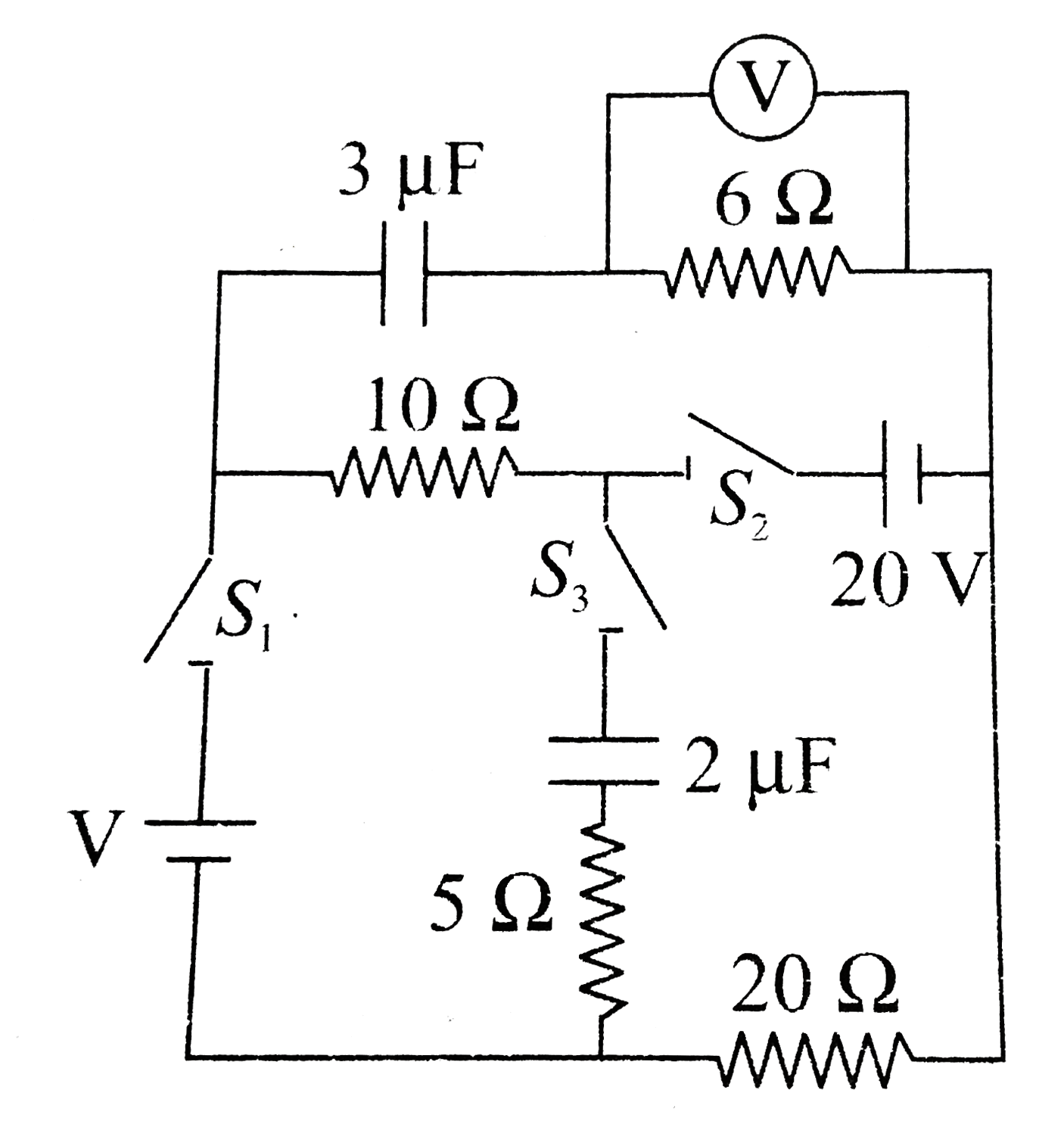
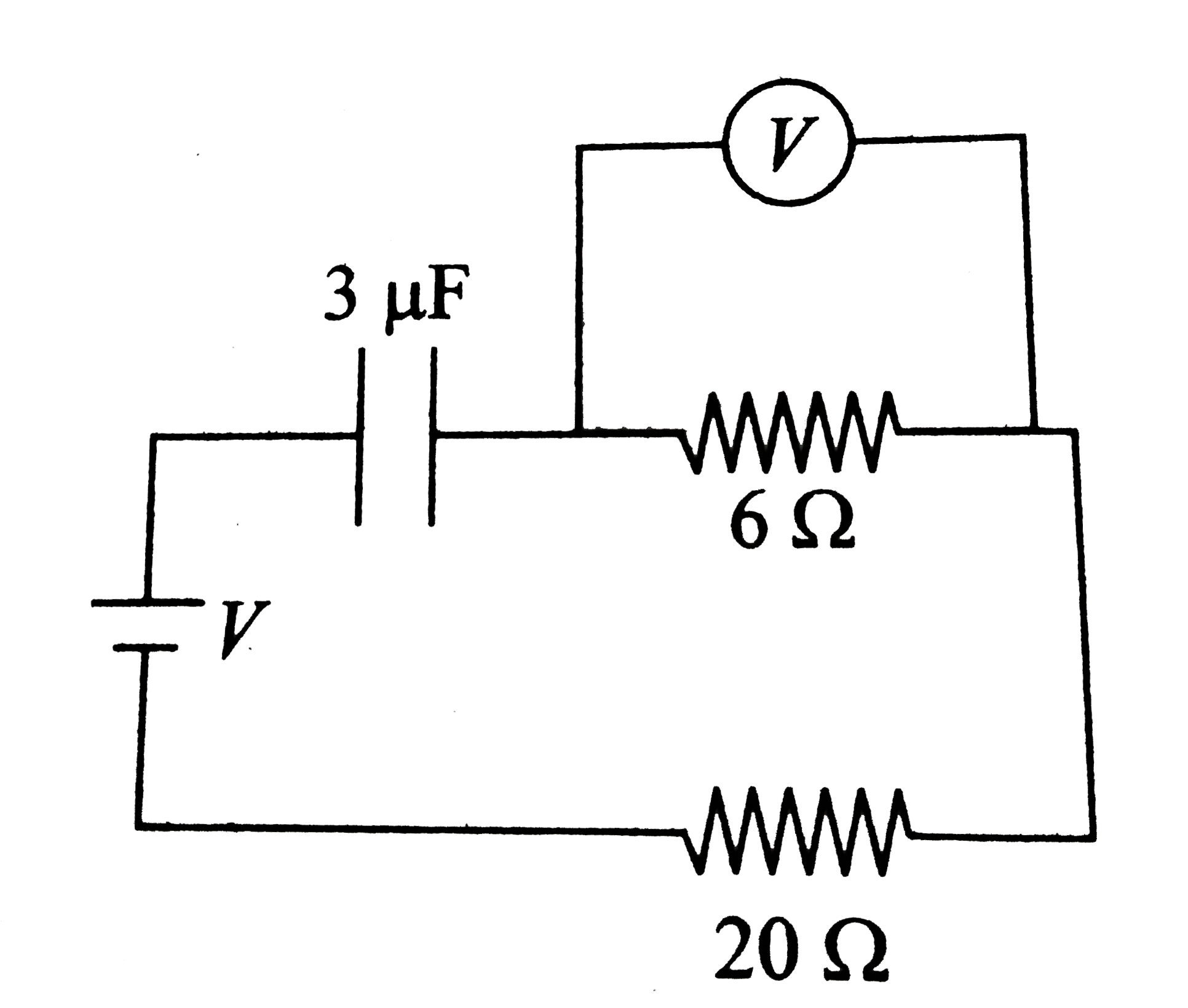
  14. Only switch S1 closed in fig. a. what is the steady-state reading of...

    Text Solution

    |

  15. A point charge +q is moved with a constant velocity v toward a solid c...

    Text Solution

    |

  16. Calculate equivalent resistance between A and B of the circuit shown i...

    Text Solution

    |

  17. In the circuit shown in fig. calculate the following: a. Potential d...

    Text Solution

    |

  18. In the given cirucit, determine current through branch having indicate...

    Text Solution

    |

  19. Determine current through batteries epsilon(1) and epsilon(2)

    Text Solution

    |

  20. The cirucit shown in fig. extends to the right into infinity. Each bat...

    Text Solution

    |