A
B
C
D
Text Solution
Verified by Experts
The correct Answer is:


Topper's Solved these Questions
INDUCTANCE
CENGAGE PHYSICS|Exercise Exercises (multiple Correct )|7 VideosINDUCTANCE
CENGAGE PHYSICS|Exercise Exercises (assertion-reasoning)|2 VideosINDUCTANCE
CENGAGE PHYSICS|Exercise Exercises (subjective)|7 VideosHEATING EFFECT OF CURRENT
CENGAGE PHYSICS|Exercise Thermal Power in Resistance Connected in Circuit|28 VideosKINETIC THEORY
CENGAGE PHYSICS|Exercise Question Bank|31 Videos
Similar Questions
Explore conceptually related problems
CENGAGE PHYSICS-INDUCTANCE-Exercises (single Correct )
- Find the inductance of a unit length of two parallel wires, each of ra...
Text Solution
|
- Figure shows a rectangular coil near a long wire. The mutual inductanc...
Text Solution
|
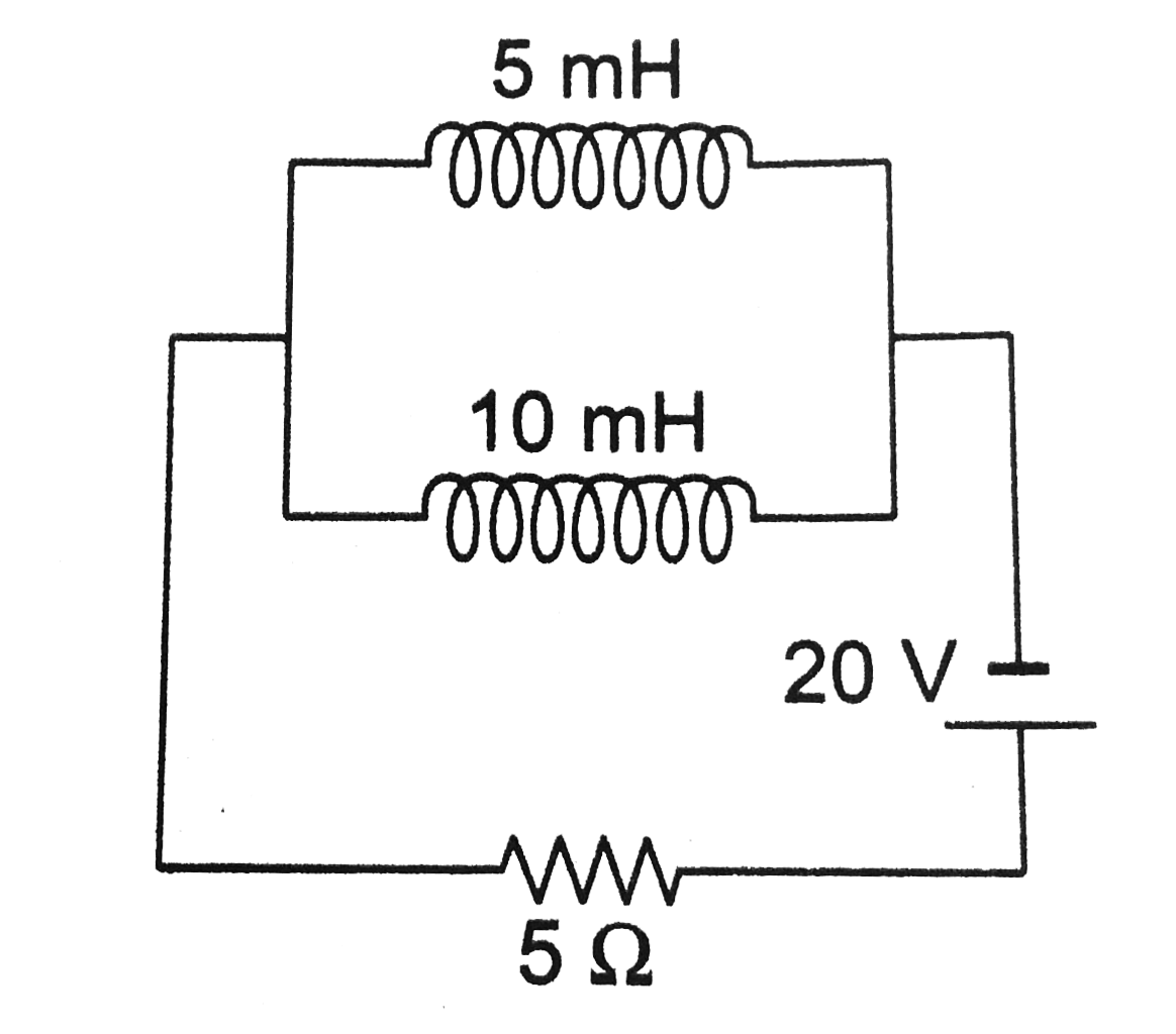
- In the given circuit, find the current through the 5 mH inductor in st...
Text Solution
|
- In the following electrical network at t = lt 0 Fig key is placed on (...
Text Solution
|
- The total heat produced in resistor r in an RL circuit when the curren...
Text Solution
|
- In the circuit shows Fig the cell is ideal. The coil has an inductance...
Text Solution
|
- In the circuit shows Fig the coil has inductance and resistance. When ...
Text Solution
|
- A long solenoid having 200 turns per centimeter carries a current of 1...
Text Solution
|
- In an LR circuit connected to a battery, the rate at which energy is s...
Text Solution
|
- Two coils are at fixed location: When coil 1 has no current and the cu...
Text Solution
|
- Two concentric and coplanar coils have redii a and b ( gt gt a) as s...
Text Solution
|
- A current i(0) is flowing through an L-R circuit of time constant i(0)...
Text Solution
|
- In the circuit shown in figure switch S is closed at time t=0. The cha...
Text Solution
|
- A bar magnet was pulled away from a hollow coil A as shows in Fig As t...
Text Solution
|
- In the given circuit (Fig), key K is witched on the at t = 0. The rati...
Text Solution
|
- A closed loop of cross-sectional area 10^(-2) m^(2) which has inductan...
Text Solution
|
- In Fig. key K is closed at t = 0. After a long time, the potential dif...
Text Solution
|
- A solenoid of inductance L with resistance r is connected in parallel ...
Text Solution
|
- The cell in the circuit shows in Fig is ideal. The coil has an inducta...
Text Solution
|
- Switch S shown in Fig. is closed for t lt 0 and is opened at t = 0. Wh...
Text Solution
|