A
B
C
D
Text Solution
Verified by Experts
The correct Answer is:


Topper's Solved these Questions
INDUCTANCE
CENGAGE PHYSICS|Exercise Exercises (integer)|8 VideosINDUCTANCE
CENGAGE PHYSICS|Exercise Archives (fills In The Blanks)|3 VideosINDUCTANCE
CENGAGE PHYSICS|Exercise Exercises (assertion-reasoning)|2 VideosHEATING EFFECT OF CURRENT
CENGAGE PHYSICS|Exercise Thermal Power in Resistance Connected in Circuit|28 VideosKINETIC THEORY
CENGAGE PHYSICS|Exercise Question Bank|31 Videos
Similar Questions
Explore conceptually related problems
CENGAGE PHYSICS-INDUCTANCE-Exercises (linked Compreshension)
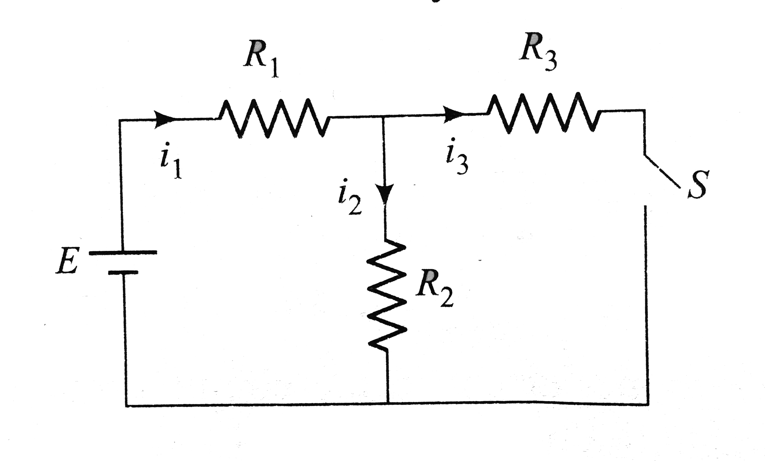
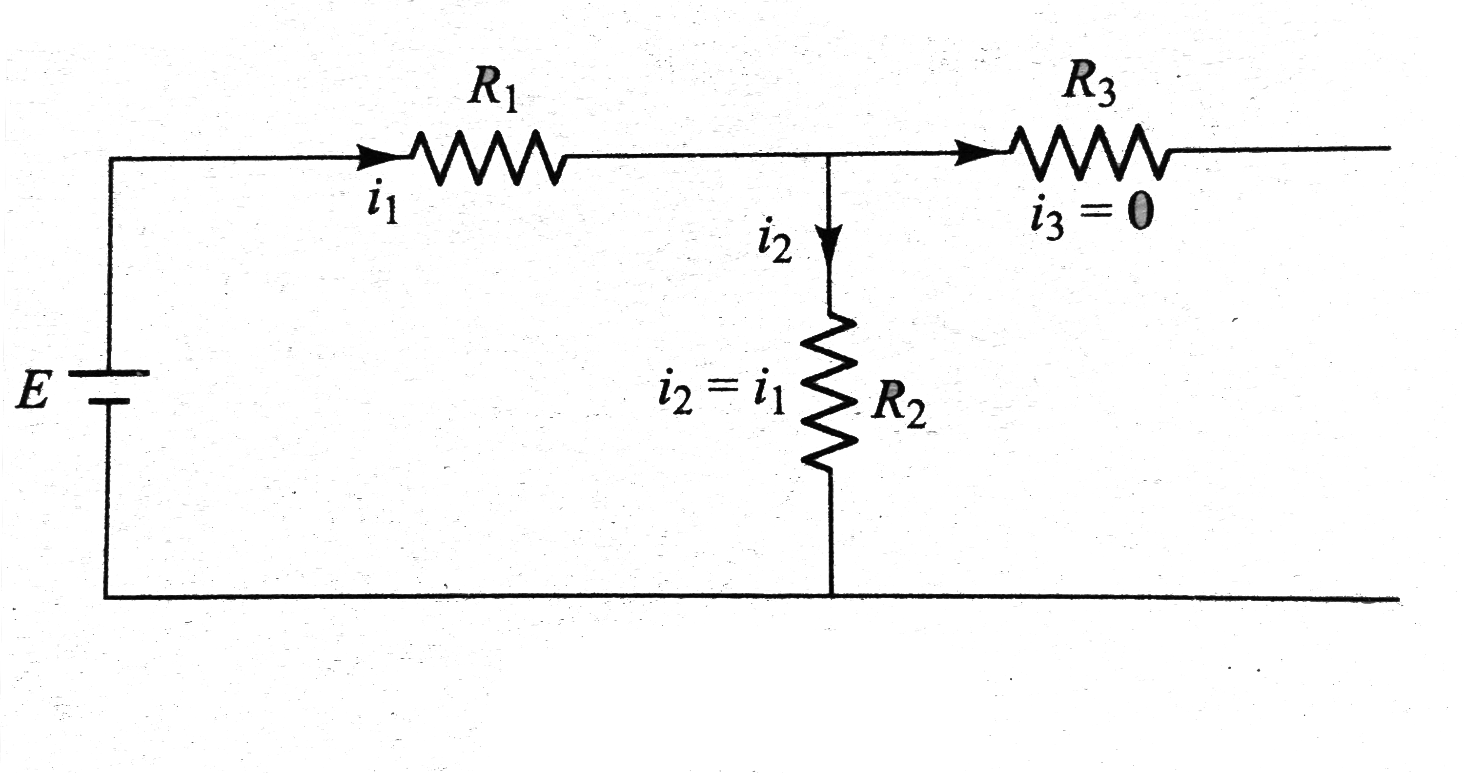
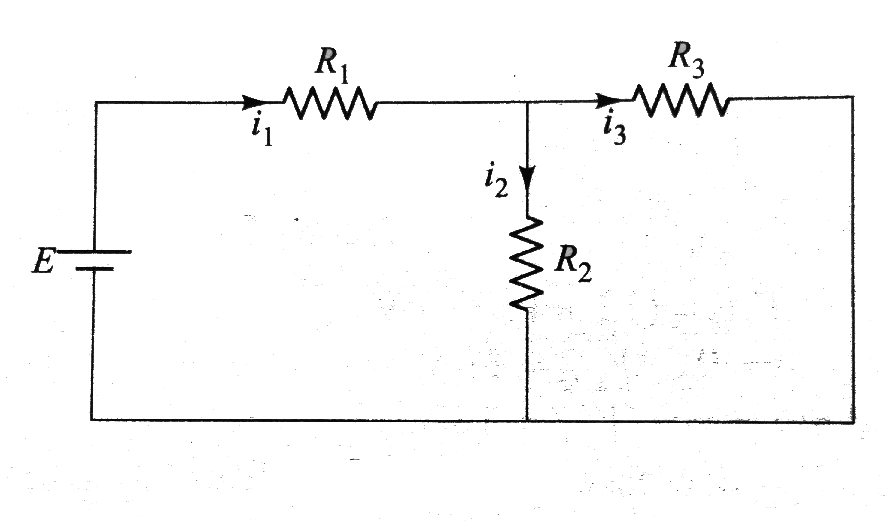
- In the circuit shows in Fig E = 15 V, R(1) = 1Omega, R(2) = 1 Omega, R...
Text Solution
|
- In the circuit shows in Fig E = 15 V, R(1) = 1Omega, R(2) = 1 Omega, R...
Text Solution
|
- In the circuit shows in Fig E = 15 V, R(1) = 1Omega, R(2) = 1 Omega, R...
Text Solution
|
- In the given at t = 0, switch S is closed. The current through th...
Text Solution
|
- In the given at t = 0, switch S is closed. The energy stored in t...
Text Solution
|
- In the given at t = 0, switch S is closed. The energy stored in t...
Text Solution
|
- In Fig. there is a frame consisting of two square loops having resist...
Text Solution
|
- In Fig. there is a frame consisting of two square loops having resist...
Text Solution
|
- In Fig. there is a frame consisting of two square loops having resist...
Text Solution
|
- there in no current part of this circuit for time t lt o. Switch S is ...
Text Solution
|
- there in no current part of this circuit for time t lt o. Switch S is ...
Text Solution
|
- there in no current part of this circuit for time t lt o. Switch S is ...
Text Solution
|
- Two capacitors of capacitance C and 3C are charged to potential differ...
Text Solution
|
- Two capacitors of capacitance C and 3C are charged to potential differ...
Text Solution
|
- Two capacitors of capacitance C and 3C are charged to potential differ...
Text Solution
|
- In Fig. there is a conducting loop ABCDEF of resistance lambda per uni...
Text Solution
|
- In Fig. there is a conducting loop ABCDEF of resistance lambda per uni...
Text Solution
|
- In Fig. there is a conducting loop ABCDEF of resistance lambda per uni...
Text Solution
|
- Initially, the capacitor is charged to a potential of 5 V and then con...
Text Solution
|
- Initially, the capacitor is charged to a potential of 5 V and then con...
Text Solution
|