A
B
C
D
Text Solution
Verified by Experts
The correct Answer is:


Topper's Solved these Questions
ALTERNATING CURRENT
CENGAGE PHYSICS|Exercise Exercises Multiple Correct|5 VideosALTERNATING CURRENT
CENGAGE PHYSICS|Exercise Exercises Assertion-reasoning|7 VideosALTERNATING CURRENT
CENGAGE PHYSICS|Exercise Exercises Subjective|15 VideosOSCILLATIONS
CENGAGE PHYSICS|Exercise QUESTION BANK|39 VideosATOMIC PHYSICS
CENGAGE PHYSICS|Exercise ddp.4.3|15 Videos
Similar Questions
Explore conceptually related problems
CENGAGE PHYSICS-ALTERNATING CURRENT-Exercises Single Correct
- In the circuit shown in fig. R is a pure resistor, L is an inductor of...
Text Solution
|
- For the circuit shown in fig, the ammeter A(2) reads 1.6A and ammeter ...
Text Solution
|
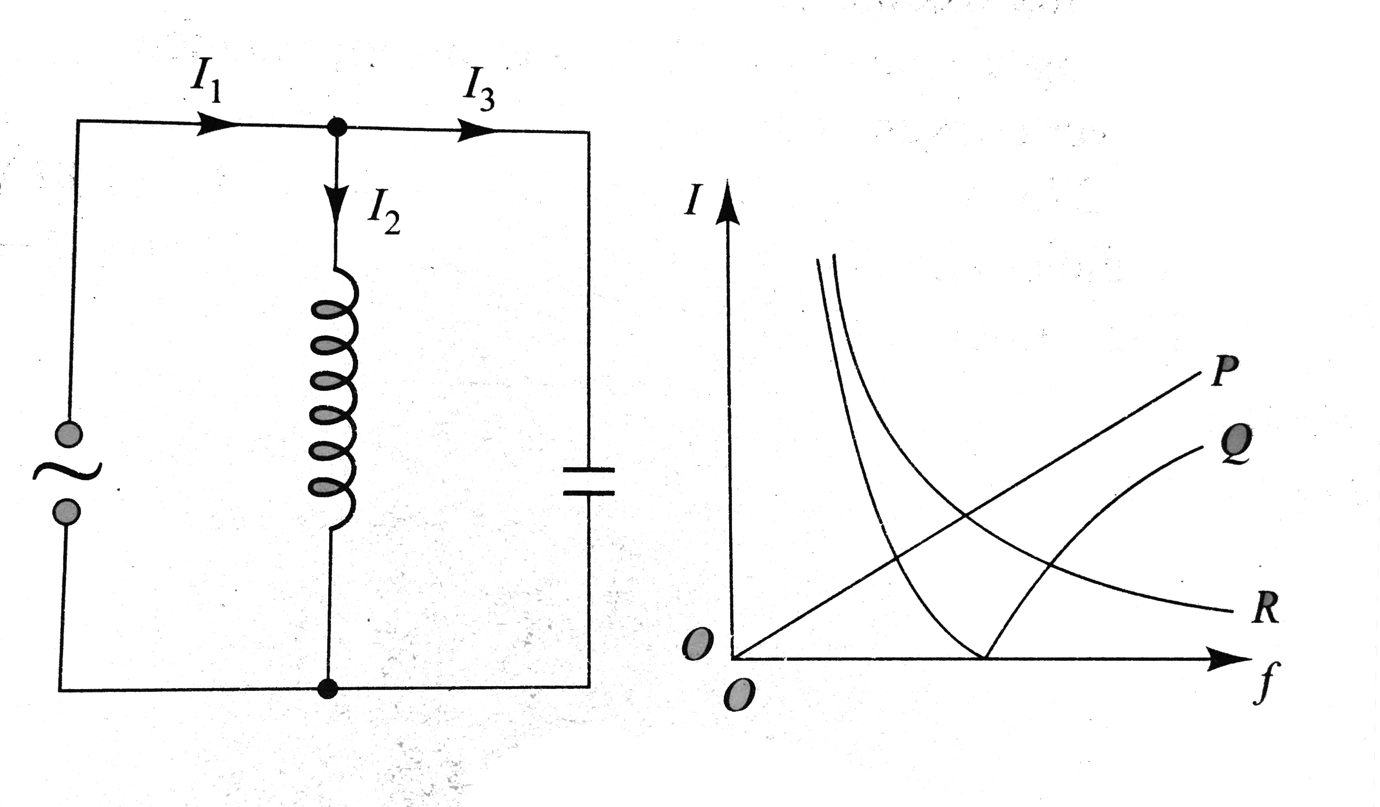
- In the circuit shown if fig, the rims currents (I1), (I2) and (I3) are...
Text Solution
|
- Two resistor are connected in series across a 5 V rms source of altern...
Text Solution
|
- In the circuit shown in fig. if both the bulbs (B1) and (B2) are ident...
Text Solution
|
- figure, shows a source of alternating voltage connected to a capacitor...
Text Solution
|
- A sinusoidal alternating current of peak value (I0) passes through a h...
Text Solution
|
- Power factor is one for
Text Solution
|
- A resonance of 20 Omega is connected to a source of an alternating pot...
Text Solution
|
- In LCR circuit currnet resonant frequency is 600Hz and half power poin...
Text Solution
|
- An ac voltage is represented by E=220 sqrt(2) cos (50 pi) t How m...
Text Solution
|
- A resistor and an inductor are connected to an ac supply of 120 V and ...
Text Solution
|
- A transmitter transmits at a wavelength of 300 m. A condenser of capac...
Text Solution
|
- A capasitor of capacitance 1 (mu)F is charged to a potential of 1 V, i...
Text Solution
|
- Using an ac voltmeter, the potential difference in the electrical line...
Text Solution
|
- An inductor and a resistor are connected in series with an ac source. ...
Text Solution
|
- A resistor and a capacitor are connected to an ac supply of 200 V, 50 ...
Text Solution
|
- In the above question, the capacitive reactance in the circuit is
Text Solution
|
- In the above question, the capacitance in the circuit is
Text Solution
|
- In a series LCR circuit, the voltage across the resistance, capactianc...
Text Solution
|