Home
Class 12
PHYSICS
In the circuit given in fig. (VC)=50 V a...

In the circuit given in fig. `(V_C)=50 V and R=50 Omega`. The values of C and `(V_R)` are

A

(A) `3.3 mF`, `60 V`

B

(B) `104 muF`, `98 V`

C

(C) `52 muF`, `98 V`

D

(D) `2 muF`, `60 V`

Text Solution

Verified by Experts

The correct Answer is:
B

`V_(C )^(2)+V_(R )^(2) =V^(2)`

`50^(2) +V_(R)^(2) = 110^(2) implies V_(R ) = sqrt(160 xx 60 ) = 98 V`
then, `(I_V) = (sqrt(160 xx 60))/(50) R = 50 Omega`
alos `(I_V) =(110)/(sqrt(R^(2)+X_(C )^(2)) :. 98/50 =(110)/(50^(2)+X_(C )^(2))`
Flux, `(X_C)` and now using `(X_C)=(1)/(omegaC)`, we get `C=104 (mu)F`.
Promotional Banner

Topper's Solved these Questions

  • ALTERNATING CURRENT

    CENGAGE PHYSICS|Exercise Exercises Multiple Correct|5 Videos
  • ALTERNATING CURRENT

    CENGAGE PHYSICS|Exercise Exercises Assertion-reasoning|7 Videos
  • ALTERNATING CURRENT

    CENGAGE PHYSICS|Exercise Exercises Subjective|15 Videos
  • OSCILLATIONS

    CENGAGE PHYSICS|Exercise QUESTION BANK|39 Videos
  • ATOMIC PHYSICS

    CENGAGE PHYSICS|Exercise ddp.4.3|15 Videos

Similar Questions

Explore conceptually related problems

A series LCR circuit is connected top an AC power source of 220 V , 50 Hz. The values of L and R are 0.41 H and 80 Omega respectively. What is the value of C if current and voltage are in phase ?

In the circuit shown in fig. R_(1) = 10 Omega, R_(2) = Omega, C_(1) = 1 muF, C_(2) = 2muF, and E =6V. Calculate the charge on each capactor in the stedy state.

In the circuit shown in figure, E = 10 V, r = 1Omega , R = 4Omega and L = 5H. The circuit is closed at time t = 0. Then, match the following two columns. {:(,"Column I",,"Column II"),(A.,V_(AD)" at t = 0",p,4 V),(B.,V_(BC)" at t = 0",q,8 V),(C.,V_(AB)" at t ="oo,r.,0V),(D.,V_(AD)" at t"=oo,s.,10V):}

In the circuit shown in figure R_1=30Omega, R_2=40 Omega, L=0.4H and C=1/3mF . Find seven function of time I, I_1, I_2, V_(R_1), V_L, V_(R_2) and V_C . Also total power consumed in the circuit. In the given potential function V is in volts and omega in rad//s .

Find a potentail difference varphi_(1) - varphi_(2) between points 1 and 2 of the circuit shown in Fig if R_(1) 1= 10 Omega, R_(2) = 20 Omega, E_(1) = 5.0 V , and E_(2) = 2.0 V . The internal resisances of the current sources are negligible.

200 V ac source is fed to series LCR circuit having X_(L)=50 Omega, X_(C )=50 Omega and R = 25 Omega . Potential drop across the inductor is

Determine the voltage drop across the resistor R_1 in the circuit given below with E = 65V, R_1 = 50 OmegaR_2 = 100 Omega, R_3 = 100 Omega, and R_4 300 Omega.

In the circuit shown in Fig. 4.19. R_(1)=100 Omega, R_(2)=R_(3)=50 Omega, R_(4)=75 Omega and E=4.75 V. Work out the equivalent resistance of the circuit and the current in each resistor.

In the adjacent circuit the ammeter reads 5.0 A and voltmeter reads 20V. The value of resistance R is

In the circuit shwon in figure, ammeter and voltmeter are ideal. E = 4 V, R = 15 Omega and r = 1 Omega , then reading of ammter (in A ) and voltmeter (in V) respectively are:

CENGAGE PHYSICS-ALTERNATING CURRENT-Exercises Single Correct
  1. In the circuit of fig, the source freqency is omega=2000 rad s^(-1). T...

    Text Solution

    |

  2. An rms voltage of 110 V is applied across a series circuit having a re...

    Text Solution

    |

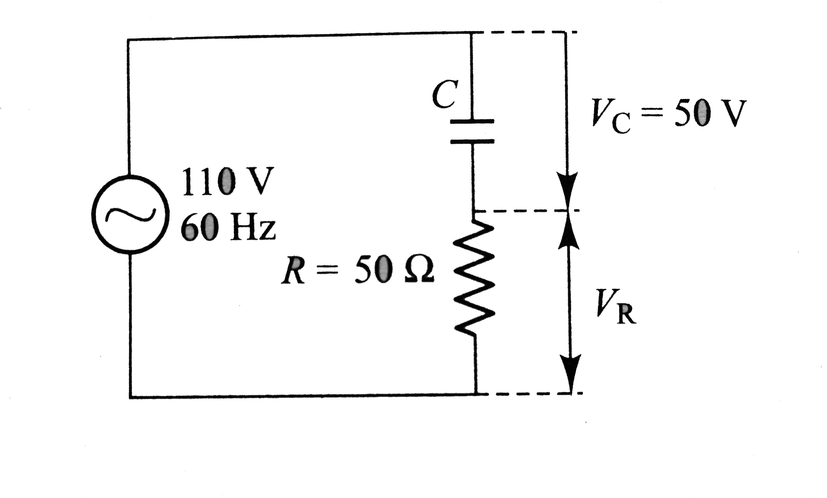
  3. In the circuit given in fig. (VC)=50 V and R=50 Omega. The values of C...

    Text Solution

    |

  4. A 220-V, 50 Hz, ac generator is connected to an inductor and a 50 Omeg...

    Text Solution

    |

  5. An 8 (mu)F capacitor is connected across a 220 V, 50 Hz line. What is ...

    Text Solution

    |

  6. A dc ammeter and a hot wire ammeter are connected to a circuit in seri...

    Text Solution

    |

  7. An alternating current is given by I = i1 cos omegat + i2 sin omegat...

    Text Solution

    |

  8. A typical light dimmer used to dim the stage lights in a theater consi...

    Text Solution

    |

  9. Two alternating voltage generators produce emfs of the same amplitude(...

    Text Solution

    |

  10. For the circuit shown in fig, current in inductance is 0.8A while that...

    Text Solution

    |

  11. If a direct current of value a ampere is superimposed on an alternativ...

    Text Solution

    |

  12. Determine the rms value of a semi-circular current wave which has a ma...

    Text Solution

    |

  13. An alternating voltage E=200sqrt(2) sin (100 t)V is connected to a 1 (...

    Text Solution

    |

  14. Which voltmeter will give zero reading at resonance?

    Text Solution

    |

  15. A 50 W, 100V lamp is to be connected to an ac mains of 200V, 50 Hz. Wh...

    Text Solution

    |

  16. A capacitor of 10 (mu)F and an inductor of 1 H are joined in series. A...

    Text Solution

    |

  17. If i(1)=3 sin omega t and (i2) = 4 cos omega t, then (i3) is

    Text Solution

    |

  18. When an ac source of emfe=E(0) sin (100 t) is connected across a circu...

    Text Solution

    |

  19. In an ac circuit the potential differences across an inductance and re...

    Text Solution

    |

  20. Current in an ac circuit is given by I= 3 sin omega t + 4 cos omega t,...

    Text Solution

    |