A
B
C
D
Text Solution
Verified by Experts
The correct Answer is:


Topper's Solved these Questions
ALTERNATING CURRENT
CENGAGE PHYSICS|Exercise Exercises Assertion-reasoning|7 VideosALTERNATING CURRENT
CENGAGE PHYSICS|Exercise Exercises Linked Comprehension|25 VideosALTERNATING CURRENT
CENGAGE PHYSICS|Exercise Exercises Single Correct|63 VideosOSCILLATIONS
CENGAGE PHYSICS|Exercise QUESTION BANK|39 VideosATOMIC PHYSICS
CENGAGE PHYSICS|Exercise ddp.4.3|15 Videos
Similar Questions
Explore conceptually related problems
CENGAGE PHYSICS-ALTERNATING CURRENT-Exercises Multiple Correct
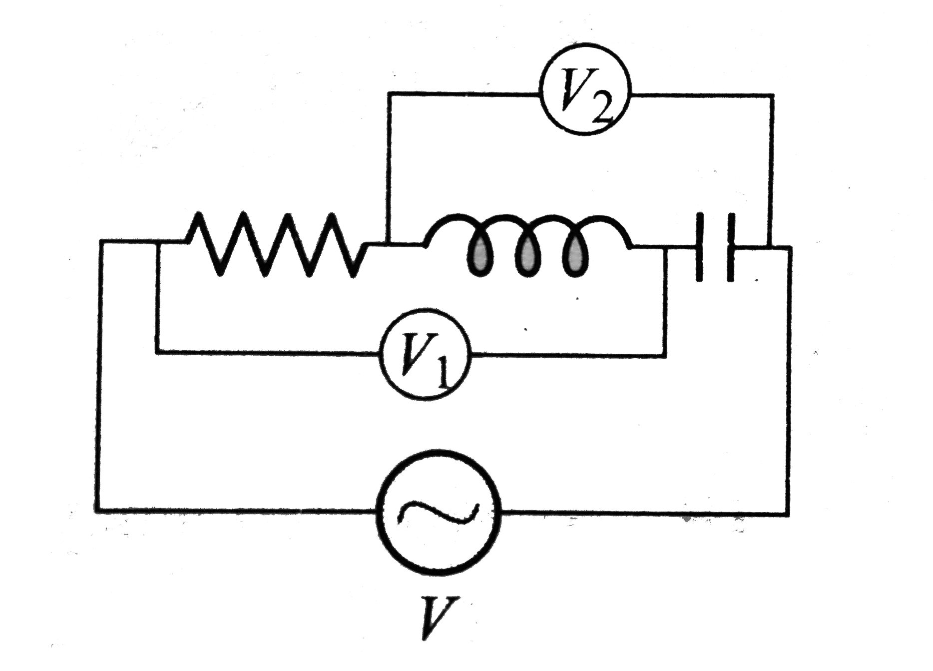
- In an ac circuit shown in fig , the supply voltage has a constant rms ...
Text Solution
|
- Resonance occures in a series LCR circuit when the frequency of the ap...
Text Solution
|
- Which of the following statements is true? Heat produced in a current...
Text Solution
|
- A choke coil of resistance 5 Omega and inductance 0.6 H is in series w...
Text Solution
|
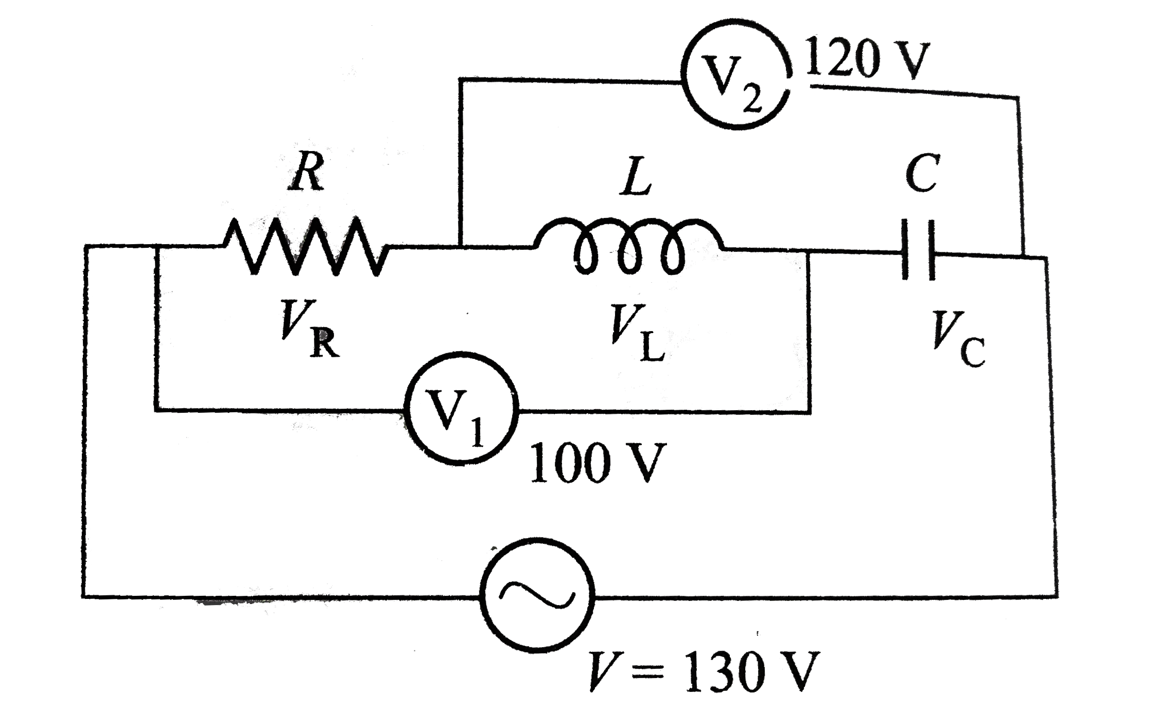
- In an RLC series circuit shown in fig. the reading of voltmeters (V1) ...
Text Solution
|