A
B
C
D
Text Solution
Verified by Experts
The correct Answer is:


Topper's Solved these Questions
ALTERNATING CURRENT
CENGAGE PHYSICS|Exercise Exercises Integer|4 VideosALTERNATING CURRENT
CENGAGE PHYSICS|Exercise Archives Subjective|1 VideosALTERNATING CURRENT
CENGAGE PHYSICS|Exercise Exercises Assertion-reasoning|7 VideosOSCILLATIONS
CENGAGE PHYSICS|Exercise QUESTION BANK|39 VideosATOMIC PHYSICS
CENGAGE PHYSICS|Exercise ddp.4.3|15 Videos
Similar Questions
Explore conceptually related problems
CENGAGE PHYSICS-ALTERNATING CURRENT-Exercises Linked Comprehension
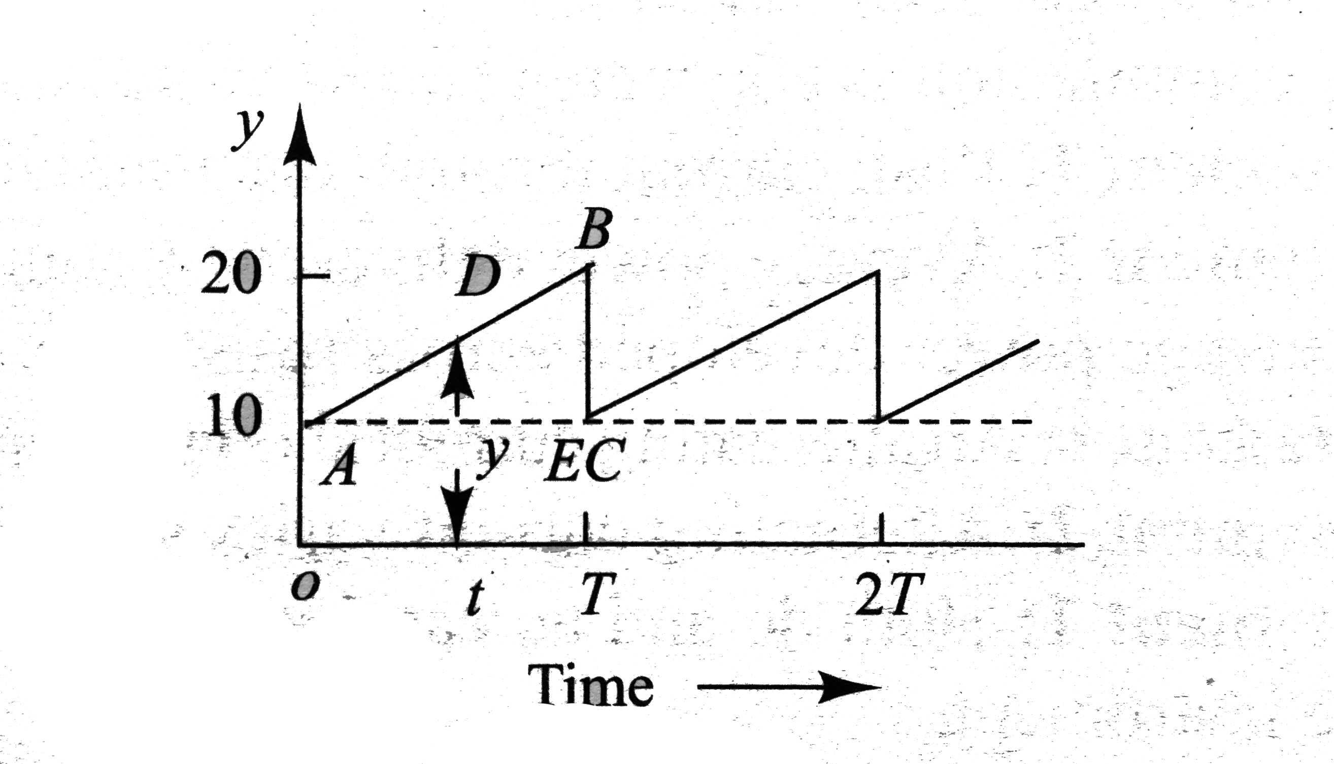
- The half cycle of an alternating singnal is shown in fig. It increases...
Text Solution
|
- The half cycle of an alternating singnal is shown in fig. It increases...
Text Solution
|
- The average value of the wave-from shown in fig. is
Text Solution
|
- The rms value of the signal is
Text Solution
|
- A 0.21 H inductor and a 12 Omega resistance are connected in series t...
Text Solution
|
- A 0.21 H inductor and a 12 Omega resistance are connected in series t...
Text Solution
|
- When 100 V dc is applied across a coil, a current of 1A flows through ...
Text Solution
|
- When 100 V dc is applied across a coil, a current of 1A flows through ...
Text Solution
|
- A box P and a coil Q are connected in series with an ac source of vari...
Text Solution
|
- A box P and a coil Q are connected in series with an ac source of vari...
Text Solution
|
- A box P and a coil Q are connected in series with an ac source of vari...
Text Solution
|
- A box P and a coil Q are connected in series with an ac source of vari...
Text Solution
|
- A series LCR circuit containing a resistance of 120 Omega has angular ...
Text Solution
|
- A series LCR circuit containing a resistance of 120 Omega has angular ...
Text Solution
|
- A series LCR circuit containing a resistance of 120 Omega has angular ...
Text Solution
|
- A current of 4 A flows in a coil when connected to a 12 V dc source. I...
Text Solution
|
- A current of 4 A flows in a coil when connected to a 12 V dc source. I...
Text Solution
|
- An inductor 20xx10^(-3) a capacitor 100(mu)F and a resistor 50 Omega a...
Text Solution
|
- An inductor 20xx10^(-3) a capacitor 100(mu)F and a resistor 50 Omega a...
Text Solution
|
- In fig, a square loop consisting of an inductor of inductance L and re...
Text Solution
|