A
B
C
D
Text Solution
Verified by Experts
The correct Answer is:


Topper's Solved these Questions
MISCELLANEOUS VOLUME 5
CENGAGE PHYSICS|Exercise Linked Comprehension|84 VideosMISCELLANEOUS VOLUME 5
CENGAGE PHYSICS|Exercise Integer|12 VideosMISCELLANEOUS VOLUME 5
CENGAGE PHYSICS|Exercise Integer|12 VideosMISCELLANEOUS VOLUME 3
CENGAGE PHYSICS|Exercise True and False|3 VideosMoving charges and magnetism
CENGAGE PHYSICS|Exercise Question Bank|20 Videos
Similar Questions
Explore conceptually related problems
CENGAGE PHYSICS-MISCELLANEOUS VOLUME 5-Multiple Correct
- There are two coils A and B as shown in Fig.
Text Solution
|
- The current in a certain circuit varies with time as shown in figure. ...
Text Solution
|
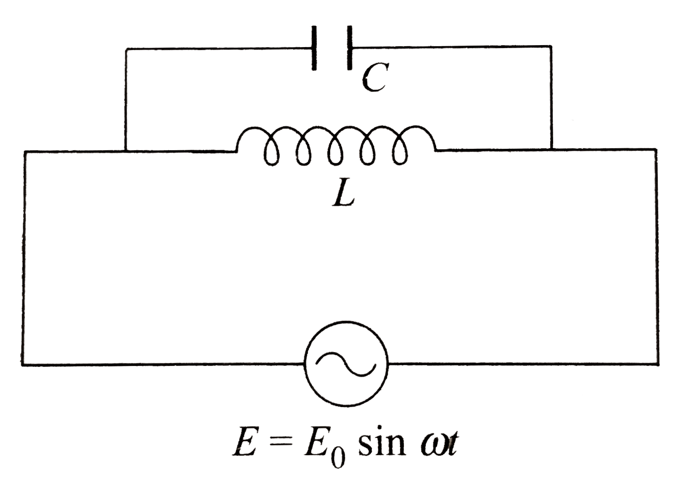
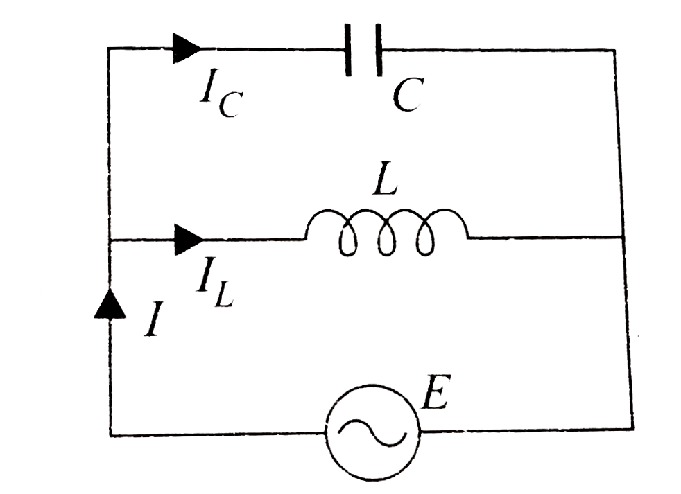
- For the circuit shown in Fig. the emf of the generator is E. The curre...
Text Solution
|
- A semicircle conducting ring of radius R is placed in the xy plane, as...
Text Solution
|
- A bar magnet is moved along the axis of a copper ring placed far away ...
Text Solution
|
- Two long parallel wires, AB and CD, carry equal currents in opposite d...
Text Solution
|
- L is a circular loop (in y-z plane) carrying an anticlockwise current....
Text Solution
|
- A straight wire carrying current is parallel to the y-axis as shown in...
Text Solution
|
- A square conducting loop is placed in the neighbourhood of a coplaner ...
Text Solution
|
- A conducting rod of length is moved at constant velocity v(0) on two p...
Text Solution
|
- A rectangular coil 20 cm xx 10 cm having 500 turns rotates in a magnet...
Text Solution
|
- Uniform magnetic field B =5 T is acting in the region of length L=5 m ...
Text Solution
|
- In the figure shown R = 100 Omega L = (2)/(pi) H and C = (8)/(pi) mu F...
Text Solution
|
- In a region there exists a magnetic field B(0) along positive x-axis. ...
Text Solution
|
- An LR circuit with a battery is connected at t=0. Which of the follow...
Text Solution
|
- The switches in figure and are closed at =0 and reopended after al ...
Text Solution
|
- L,C and R represent the physical quantities inductance, capacitance an...
Text Solution
|
- For the circuit shown in Fig. Which of the following statements are co...
Text Solution
|
- Two straight conducting rails form a right angle where their ends are ...
Text Solution
|
- The current growth in two L-R circuits (b) and (c) is as shown in Fig....
Text Solution
|