Home
Class 10
PHYSICS
Identify the circuit, (Fig.) in which th...

Identify the circuit, (Fig.) in which the electrical components have been properly connected.

A

(i)

B

(ii)

C

(iii)

D

(iv)

Text Solution

Verified by Experts

The correct Answer is:
B

(i) Positive terminals of `V and A` should be joined to positive terminal of the cell and their negative terminals should be joined to the negative terminal of the cell. (ii) The voltmeter (V) should be connected in parallel and the ammeter (A) should be connected in series. These conditions are satisfied in (Fig.3) (ii).
Promotional Banner

Topper's Solved these Questions

  • ELECTRICITY

    PRADEEP|Exercise (Mock Test)Sec -A|21 Videos
  • ELECTRICITY

    PRADEEP|Exercise (Mock Test)Sec - B|6 Videos
  • ELECTRICITY

    PRADEEP|Exercise Problem For Practice|59 Videos
  • MAGNETIC EFFECTS OF ELECTRIC CURRENT

    PRADEEP|Exercise Mock Test|21 Videos

Similar Questions

Explore conceptually related problems

Name the electrical components having the following symbols :

Name the type in which the electronic circuit have been classified.

Two students made two circuits A and B to determine the resultant resistance of two resistors R_(1) and R_(2) connected in series : All the components have been connected correctly in :

For the circuit shown in Fig. Which of the following statements are correct?

For three circuits, shown here the same two resistors R_(1) and R_(2) have been connected in parallel in all the circuits but the voltmeter and the ammeter have been connected in three different positions. The relation between the three voltmeter and ammeter readings would be :

For the circuit shows in Fig which of the following statements is //are correct?

In the experiment on finding the equivalent resistance of two resistors connected in series, three students connected the ammeter in their circuits in the three ways X, Y and Z shown here. Assuming their ammeters to be ideal, the ammeters have been correctly connected in

PRADEEP-ELECTRICITY-(Exemplar)Multiple Choice
  1. A cell, a resistor, a key and an ammeter are arranged as shown in the ...

    Text Solution

    |

  2. In the following circuits, (Fig. 3.38), heat produced in the resistor ...

    Text Solution

    |

  3. Electrical resistivity of a given metallic wire depends upon :

    Text Solution

    |

  4. A current of 1 A is drawn by a filament of an electric bulb. Number of...

    Text Solution

    |

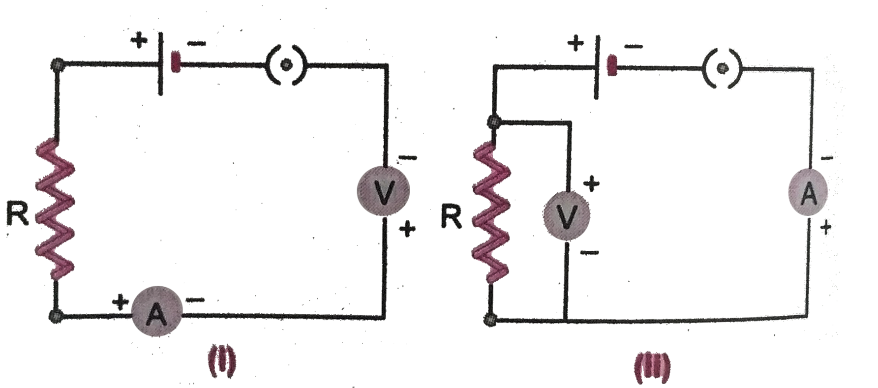
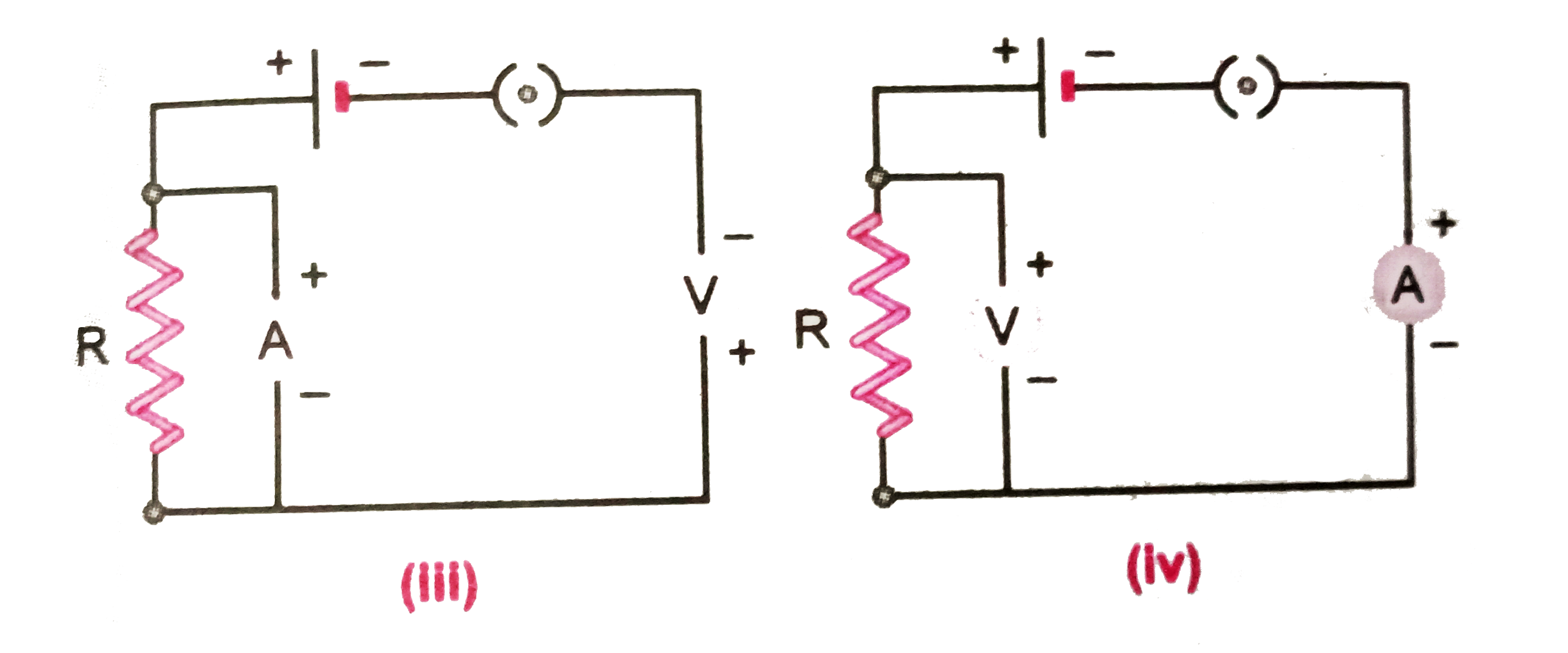
  5. Identify the circuit, (Fig.) in which the electrical components have b...

    Text Solution

    |

  6. What is the maximum resistance which can be made using five resistors ...

    Text Solution

    |

  7. What is the minimum resistance which can be made using five resistors ...

    Text Solution

    |

  8. The proper representation of series combination of cells, (Fig. 3.40) ...

    Text Solution

    |

  9. Which of the following represents voltage ?

    Text Solution

    |

  10. A cylindrical conductor of length l and uniform area of cross-section ...

    Text Solution

    |

  11. A student carries out an experiment and plots the V-I graphs of three ...

    Text Solution

    |

  12. If the current I through a resistor is increased by 100% (assume that ...

    Text Solution

    |

  13. The resistivity does not change if :

    Text Solution

    |

  14. In an electrical circuit three incandescent bulbs A,B and C of rating ...

    Text Solution

    |

  15. In an electrical circuit, two resistors of 2 Omega and 4 Omega respect...

    Text Solution

    |

  16. An electric kettle consumes 1 kW of electric power when operated at 22...

    Text Solution

    |

  17. Two resistors of resistances 2 Omega and 4 Omega when connected to a b...

    Text Solution

    |

  18. Unit of electric power may also be expressed as :

    Text Solution

    |