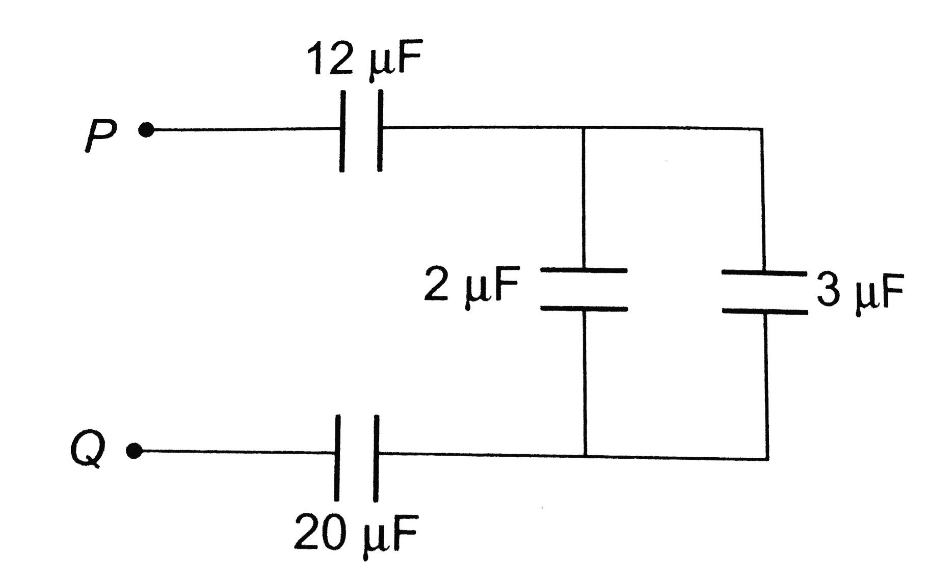
A
B
C
D
Text Solution
Verified by Experts
The correct Answer is:


Topper's Solved these Questions
ELECTRIC POTENTIAL & CAPACITANCE
A2Z|Exercise Problems Based On Mixed Concepts|44 VideosELECTRIC POTENTIAL & CAPACITANCE
A2Z|Exercise Section B - Assertion Reasoning|17 VideosELECTRIC POTENTIAL & CAPACITANCE
A2Z|Exercise Grouping Of Capacitors|48 VideosELECTRIC CHARGE, FIELD & FLUX
A2Z|Exercise Section D - Chapter End Test|29 VideosELECTROMAGNETIC INDUCTION
A2Z|Exercise Section D - Chapter End Test|30 Videos
Similar Questions
Explore conceptually related problems
A2Z-ELECTRIC POTENTIAL & CAPACITANCE-Capacitor Circuits
- Four condensers each of capacity 4mF are connected as shown in figure....
Text Solution
|
- In three capacitors C(1),C(2), and C(3), are joined to a battery, With...
Text Solution
|
- In the circuit diagram shown in the adjoining figure, the resultant ca...
Text Solution
|
- If three capacitors each of capacity 1 muF are connected in such a way...
Text Solution
|
- A capacitor of capacity C(1) is charged to the potential of V(0). On d...
Text Solution
|
- Four capacitors of each of capacity 3 muF are connected as shown in th...
Text Solution
|
- Four condensers are joined as shown in the adjoining figure. The capa...
Text Solution
|
- The capacities and connection of five capacitors are shown in the adjo...
Text Solution
|
- Three equal capacitors, each with capacitance C are connected as shown...
Text Solution
|
- In the adjoining figure, four capacitors are shown with their respecti...
Text Solution
|
- A 4 muF condenser is connected in parallel to another condenser of 8 m...
Text Solution
|
- In the connection shown in the adjoining figure, the equivalent capaci...
Text Solution
|
- The resultant capacitance between A and B in the following figure is e...
Text Solution
|
- In the following circuit, the resultant capacitance between A and B is...
Text Solution
|
- What is the equivalent capacitance between A and B in the given figure...
Text Solution
|
- In the circuit shown in the figure, the potential difference across th...
Text Solution
|
- Minimum number of capacitors of 2muF capacitance each required to obta...
Text Solution
|
- The total capacity of the system of capacitors shown in the adjoining ...
Text Solution
|
- The equivalent capactiance between A and B in the figure is 1 muF. The...
Text Solution
|
- Four capacitors are connected in a circuit as shown in the figure. The...
Text Solution
|