A
B
C
D
Text Solution
Verified by Experts
The correct Answer is:


Topper's Solved these Questions
ELECTRIC POTENTIAL & CAPACITANCE
A2Z|Exercise Problems Based On Mixed Concepts|44 VideosELECTRIC POTENTIAL & CAPACITANCE
A2Z|Exercise Section B - Assertion Reasoning|17 VideosELECTRIC POTENTIAL & CAPACITANCE
A2Z|Exercise Grouping Of Capacitors|48 VideosELECTRIC CHARGE, FIELD & FLUX
A2Z|Exercise Section D - Chapter End Test|29 VideosELECTROMAGNETIC INDUCTION
A2Z|Exercise Section D - Chapter End Test|30 Videos
Similar Questions
Explore conceptually related problems
A2Z-ELECTRIC POTENTIAL & CAPACITANCE-Capacitor Circuits
- In the given network capacitance, C(1) = 10muF, C(2) = 5 muF and C(3) ...
Text Solution
|
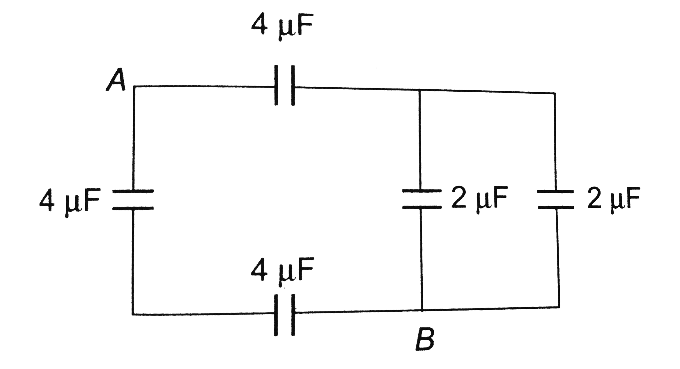
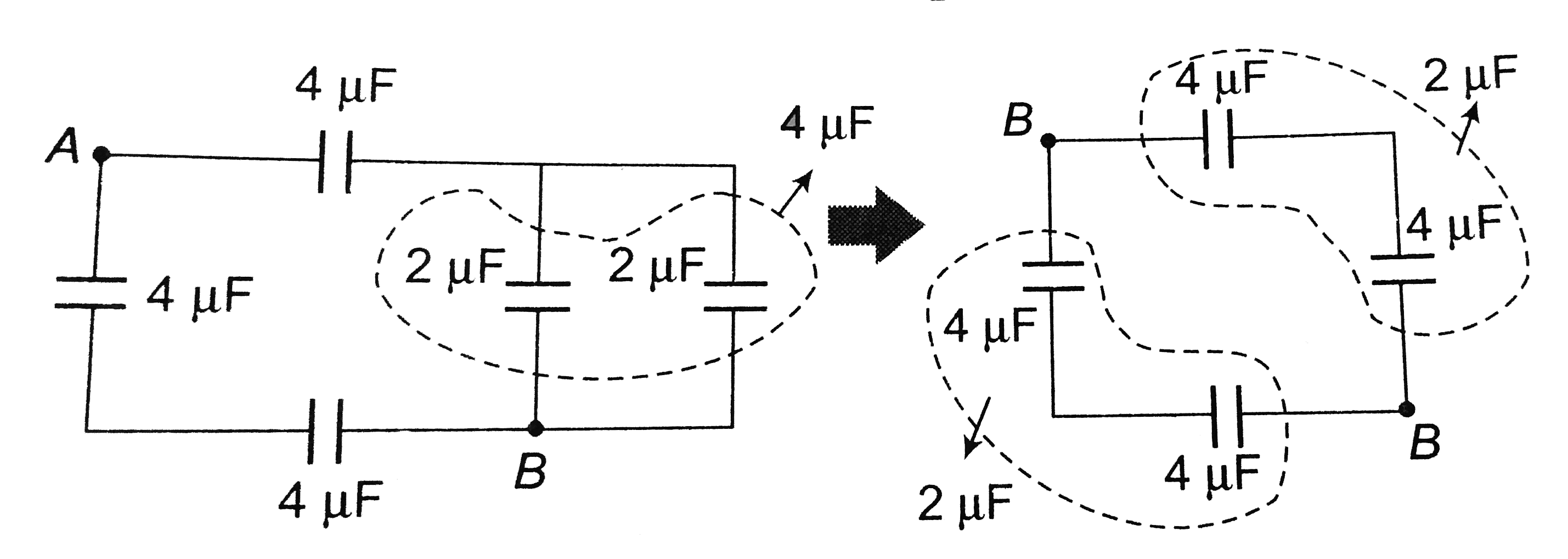
- The equivalent capacitance between A and B is
Text Solution
|
- The capacitance between the points A and B in the given circuit will b...
Text Solution
|
- In the circuit shown in figure, each capacitor has a capacity of 3 muF...
Text Solution
|
- What is the effective capacitance between A and B in the following fig...
Text Solution
|
- Two capacitors A and B are connected in series with a battery as shown...
Text Solution
|
- In the figure, three capacitors each of capacitance 6 pF are connected...
Text Solution
|
- Equivalent capacitance between A and B is
Text Solution
|
- Two capacitors C(1) = 2 muF and C(2) = 6 muF in series, are connected ...
Text Solution
|
- The equivalent capacitance in the circuit between A and B will be
Text Solution
|
- The equivalent capacitance between A and B is
Text Solution
|
- The effective capacitance between A and B in the figure given is
Text Solution
|
- The charge on any of the 2 muF capacitors and 1 muF capacitor will be ...
Text Solution
|
- In the circuit as shown in the figure the effective capacitance betwee...
Text Solution
|
- Four equal capacitors, each of capacity C, are arranged as shown. The ...
Text Solution
|
- In the figure shown, the effective capacitance between the points A an...
Text Solution
|
- In the figure a potential of + 1200 V is given to point A and point B ...
Text Solution
|
- In the given circuit, the charge on 4 mu F capacitor will be :
Text Solution
|
- Effective capacitance between A and B in the figure shown is (all capa...
Text Solution
|
- Four identical capacitors are connected as shown in diagram. When a ba...
Text Solution
|