A
B
C
D
Text Solution
Verified by Experts
The correct Answer is:


Topper's Solved these Questions
ELECTRIC POTENTIAL & CAPACITANCE
A2Z|Exercise AIIMS Questions|20 VideosELECTRIC POTENTIAL & CAPACITANCE
A2Z|Exercise Assertion Reason|8 VideosELECTRIC POTENTIAL & CAPACITANCE
A2Z|Exercise Section B - Assertion Reasoning|17 VideosELECTRIC CHARGE, FIELD & FLUX
A2Z|Exercise Section D - Chapter End Test|29 VideosELECTROMAGNETIC INDUCTION
A2Z|Exercise Section D - Chapter End Test|30 Videos
Similar Questions
Explore conceptually related problems
A2Z-ELECTRIC POTENTIAL & CAPACITANCE-AIPMTNEET Questions
- Three capacitors each of capacitance C and of breakdown voltage V are ...
Text Solution
|
- The electirc potential at a point (x, y, z) is given by V = -x^(2)y ...
Text Solution
|
- A series combination of n(1) capacitors, each of value C(1), is charge...
Text Solution
|
- A parallel plate condenser has a unifrom electric field E (V//m) in th...
Text Solution
|
- Four electric charges +q, +q, -q and -q are placed at the corners of a...
Text Solution
|
- The potential energy of a particle in a force field is: U = (A)/(r^(...
Text Solution
|
- Four point charges -Q, -q, 2q and 2Q are placed, one at each corner of...
Text Solution
|
- A, B and C are three points in a unifrom electric field. The electric ...
Text Solution
|
- Two thin dielectric slabs of dielectric constants K(1) and K(2) (K(1) ...
Text Solution
|
- A conducting sphere of radius R is given a charge Q. The electric pote...
Text Solution
|
- In a region, the potential is respresented by V(x, y, z) = 6x - 8xy - ...
Text Solution
|
- A parallel plate air capacitor of capacitance C is connected to a cell...
Text Solution
|
- A parallel plate air capacitor has capacity C distance of separation b...
Text Solution
|
- If potential (in volts) in a region is expressed as V (x, y, z) = 6xy ...
Text Solution
|
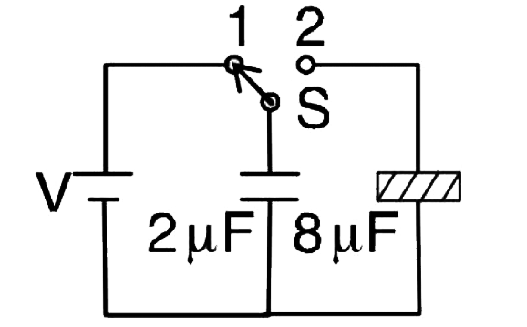
- A 2muF capacitor is charged as shown in the figure. The percentage of ...
Text Solution
|
- Two identical charged spheres suspended from a common point by two mas...
Text Solution
|
- A parallel -plate capacitor of area A, plate separation d and capacita...
Text Solution
|
- A capacitor is charged by a battery. The battery is removed and anothe...
Text Solution
|
- The diagram below show regions of equipotential: A positive chrages ...
Text Solution
|
- The electrostatic force between the metal plate of an isolated paralle...
Text Solution
|