A
B
C
D
Text Solution
Verified by Experts
The correct Answer is:


Topper's Solved these Questions
CURRENT ELECTRICITY
A2Z|Exercise R-C Circuits|17 VideosCURRENT ELECTRICITY
A2Z|Exercise Ammeter And Voltmeter|41 VideosCURRENT ELECTRICITY
A2Z|Exercise Combination And Resistivity|38 VideosATOMIC PHYSICS
A2Z|Exercise Section D - Chapter End Test|30 VideosDUAL NATURE OF RADIATION AND MATTER
A2Z|Exercise Section D - Chapter End Test|30 Videos
Similar Questions
Explore conceptually related problems
A2Z-CURRENT ELECTRICITY-Kircoff'S Laws And Simple Circuits
- A battery consists of a variable number n of identical cells having in...
Text Solution
|
- In previous problem, if the cell had been connected parallel (instead ...
Text Solution
|
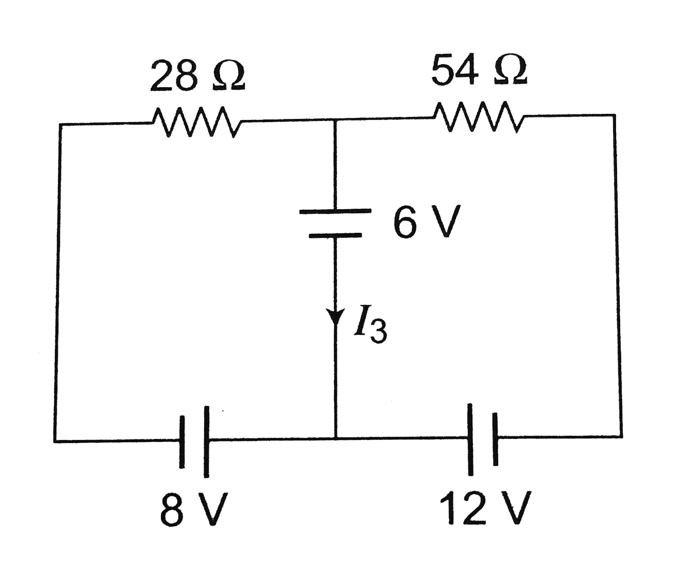
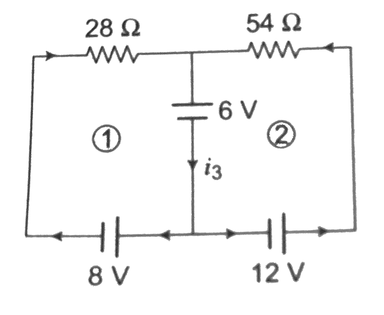
- Consider the circuit shown in the figure. The current I(3) is equal to
Text Solution
|
- In the circuit element given here, if the potential at point B = V(B) ...
Text Solution
|
- In the given circuit if I(1) and I(2) be the current in resistance R(1...
Text Solution
|
- The potential difference between points A and B adjoining figure is
Text Solution
|
- The current in the adjoining circuit will be
Text Solution
|
- The reading of the ammeter as per figure shown is
Text Solution
|
- A current of 2 A flows in a system of conductor as shown. The potentia...
Text Solution
|
- Four resistances are connected in a circuit in the given figure. The e...
Text Solution
|
- If a resistanceR(2) is connected in parallel with the resistance R in ...
Text Solution
|
- A battery of e.m.f. 10 V is connected to resistance as shown in figure...
Text Solution
|
- In the circuit shown, the point B is earthed. The potential at the poi...
Text Solution
|
- Three resistors each of 4 Omega are connected together to form a netwo...
Text Solution
|
- In the circuit shown below, the cell has an e.m.f. of 10 V and interna...
Text Solution
|
- The potential drop across the 3 Omega resistor is
Text Solution
|
- A uniform wire of resistance 9 Omega is cut into 3 equal parts. They a...
Text Solution
|
- In the circuit shown in the adjoining figure, the current between B an...
Text Solution
|
- In the figure given the value of X resistance will be, when the p.d. b...
Text Solution
|
- For what value of unknown resistance X, the potential difference betwe...
Text Solution
|