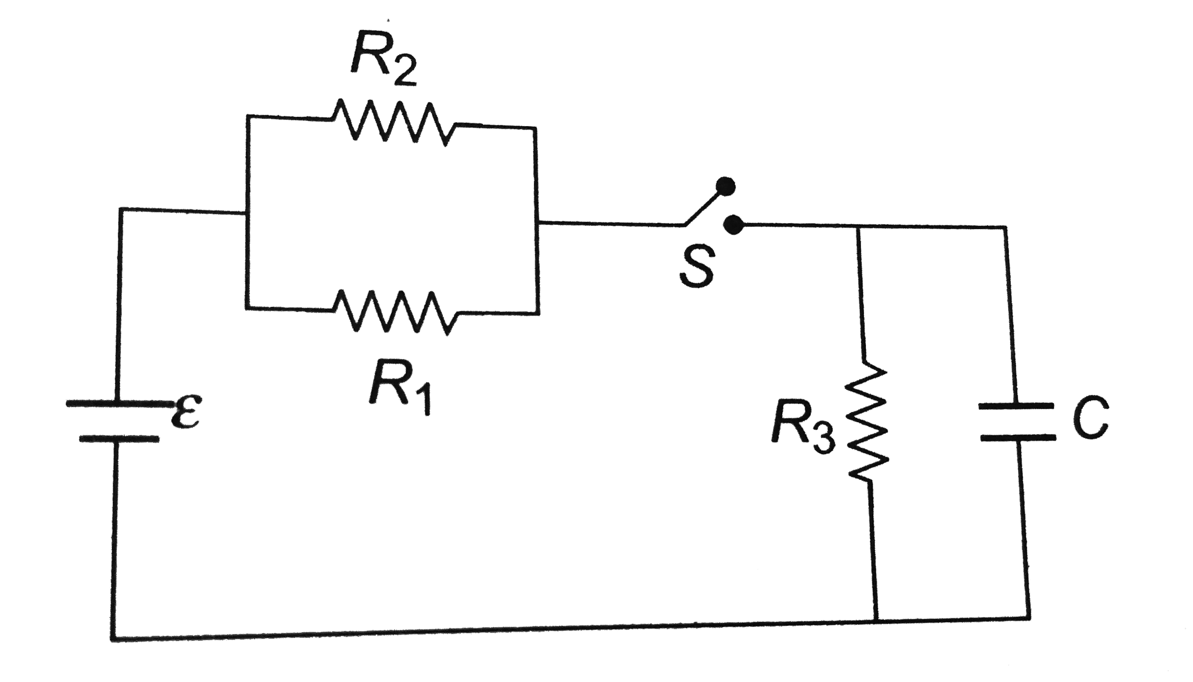
A
B
C
D
Text Solution
Verified by Experts
The correct Answer is:


Topper's Solved these Questions
CURRENT ELECTRICITY
A2Z|Exercise Ammeter And Voltmeter|41 VideosCURRENT ELECTRICITY
A2Z|Exercise Potentiometer And Meter Bridge|45 VideosCURRENT ELECTRICITY
A2Z|Exercise Kircoff'S Laws And Simple Circuits|64 VideosATOMIC PHYSICS
A2Z|Exercise Section D - Chapter End Test|30 VideosDUAL NATURE OF RADIATION AND MATTER
A2Z|Exercise Section D - Chapter End Test|30 Videos
Similar Questions
Explore conceptually related problems
A2Z-CURRENT ELECTRICITY-R-C Circuits
- Consider the circuit shown in the figure. Find the charge on capacitor...
Text Solution
|
- In the figure shown, the capacity of the consider C is 2 nu F. The cur...
Text Solution
|
- When the key E is pressed at time t = 0, which of the following statem...
Text Solution
|
- In the given circuit, with steady current, the potential drop across t...
Text Solution
|
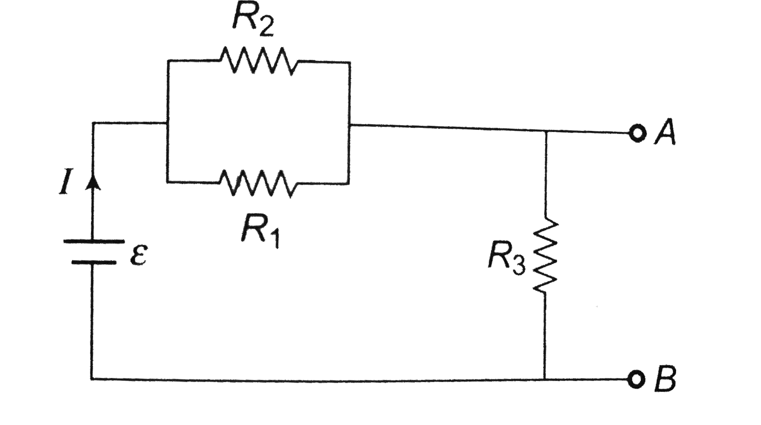
- What is the equivalent between A and B in the circuit shown ?
Text Solution
|
- In the circuit shown, S(2) is closed first and is kept closed for a lo...
Text Solution
|
- In the circuit shown in the figure, if switches S(1) and S(2) have bee...
Text Solution
|
- The circuit shown in the figure consists of a battery of emf epsilon =...
Text Solution
|
- In the circuit shown the cells are ideal and of equal emfs, the capaci...
Text Solution
|
- A capacitor of capacitance 3 mu F is first charged by connecting it ac...
Text Solution
|
- In the circuit shown switch S is closed at t=0. Let i1 and i2 be the c...
Text Solution
|
- The capacitance of the systemis C, if the key is closed, the total ene...
Text Solution
|
- In above question, the charge flown is :
Text Solution
|
- Which of the following conditions is correct in steady state ?
Text Solution
|
- The energy stored in the capacitor in the steady state is
Text Solution
|
- A capacitor is charged using an external battery with a resistance x i...
Text Solution
|
- Find the power of the circuit
Text Solution
|