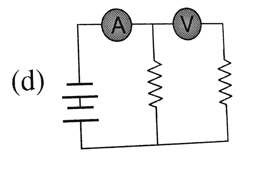
A
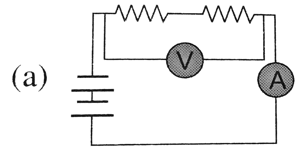
B
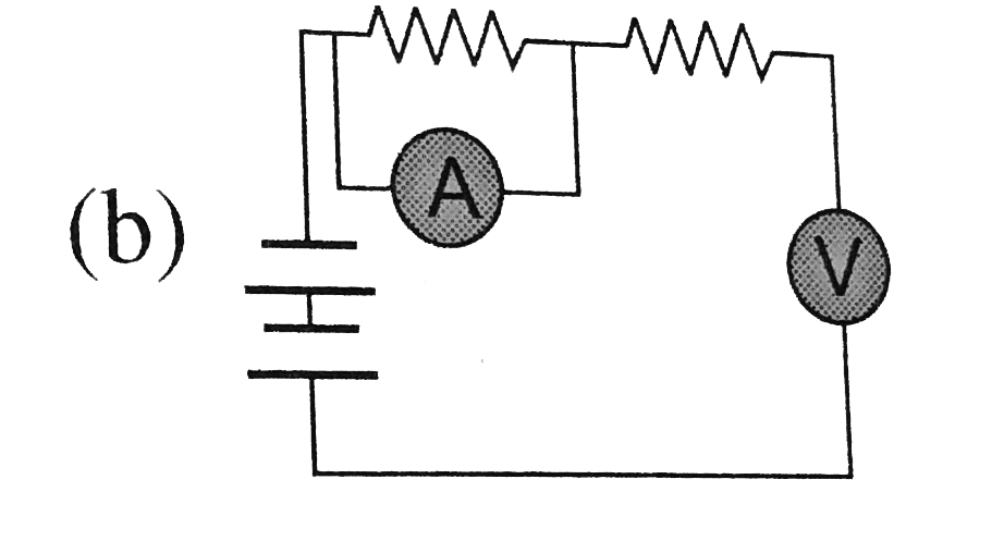
C
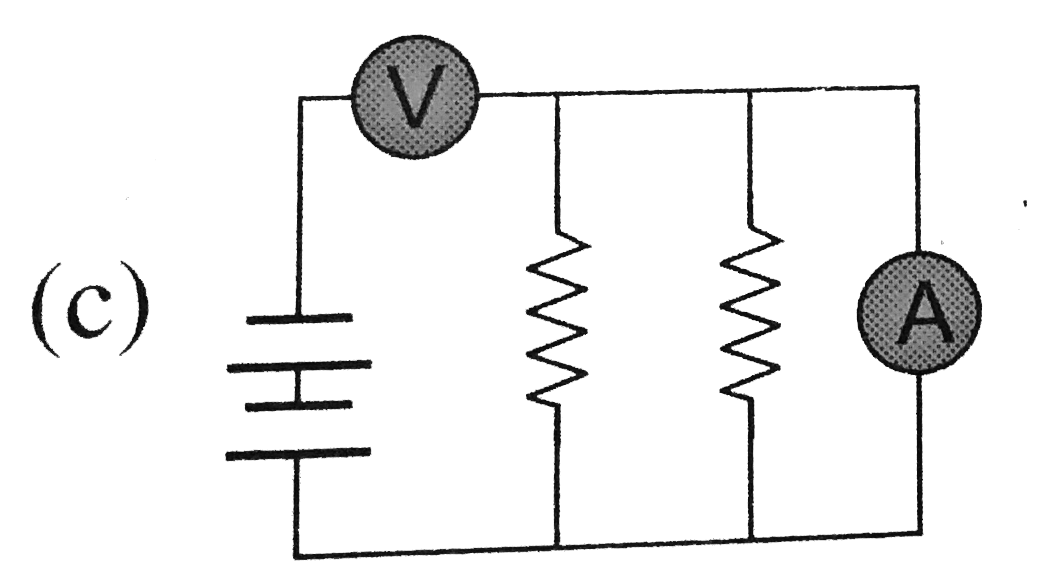
D
Text Solution
Verified by Experts
The correct Answer is:


Topper's Solved these Questions
CURRENT ELECTRICITY
A2Z|Exercise Potentiometer And Meter Bridge|45 VideosCURRENT ELECTRICITY
A2Z|Exercise Heating Effect Of Current|40 VideosCURRENT ELECTRICITY
A2Z|Exercise R-C Circuits|17 VideosATOMIC PHYSICS
A2Z|Exercise Section D - Chapter End Test|30 VideosDUAL NATURE OF RADIATION AND MATTER
A2Z|Exercise Section D - Chapter End Test|30 Videos
Similar Questions
Explore conceptually related problems
A2Z-CURRENT ELECTRICITY-Ammeter And Voltmeter
- In the circuit shown, the reading of the Ammter is doulbed after the s...
Text Solution
|
- In the adjoining circuit, the e.m.f. of the cell is 2 volt and the int...
Text Solution
|
- It is required to measure equivalent ressitance of circuit with ideal ...
Text Solution
|
- In the circuit shown the reading of ammeter and voltmeter are 4 A and ...
Text Solution
|
- Voltmeters V(1) and V(2) are connected in series across a D.C. line V(...
Text Solution
|
- Two resistance of 400 Omega and 800 Omega are connected in series with...
Text Solution
|
- A galvanometer, having a resistance of 50 Omega gives a full scale def...
Text Solution
|
- What is the reading of voltmeter in the following figure ?
Text Solution
|
- In the given circuit, the galvanmeter G will show zero deflection if
Text Solution
|
- A moving coil galvanometer has 150 equal divisions. Its current sensit...
Text Solution
|
- In the circuit shown in figure, reading of voltmeter is V1 when only S...
Text Solution
|
- In the circuit shown here, the readings of the ammeter and voltmeter a...
Text Solution
|
- Resistances R(1) and R(2) each 60 are connected in series as shown in ...
Text Solution
|
- The reading of the ideal voltmeter in the adjoining diagram will be
Text Solution
|
- In the given circuit current flowing through the resistance 20Omega is...
Text Solution
|
- The potential difference across the 100 Omega resistance in the follow...
Text Solution
|
- A voltmeter with resistance 2500 Omega indicates a voltage of 125 V in...
Text Solution
|
- The voltmeter shown in figure reads 18V across the 50(Omega)resistor. ...
Text Solution
|
- If tha ammter in the given circuit reads 2 A, the resistance R is
Text Solution
|
- Two ammeters, 1 and 2 have different internal resistances: r(1) (known...
Text Solution
|