A
B
C
D
Text Solution
Verified by Experts
The correct Answer is:


Topper's Solved these Questions
CURRENT ELECTRICITY
A2Z|Exercise Problems Based On Mixed Concepts|34 VideosCURRENT ELECTRICITY
A2Z|Exercise Section - A|1 VideosCURRENT ELECTRICITY
A2Z|Exercise Potentiometer And Meter Bridge|45 VideosATOMIC PHYSICS
A2Z|Exercise Section D - Chapter End Test|30 VideosDUAL NATURE OF RADIATION AND MATTER
A2Z|Exercise Section D - Chapter End Test|30 Videos
Similar Questions
Explore conceptually related problems
A2Z-CURRENT ELECTRICITY-Heating Effect Of Current
- What will happen when a 40 watt 220 volt lamp and 100 watt-220 volt la...
Text Solution
|
- What should be the value of resistance R in the circuit shown in figur...
Text Solution
|
- The current in C is 2 A. The rate of heat of loss in A,B and C are 1.2...
Text Solution
|
- If the length of the filament of a heater is reduced by 10%, the power...
Text Solution
|
- Two wire A and B of same meterial and mass have their lengths in the r...
Text Solution
|
- Two bulbs X and Y having same voltage rating and of power 40 watt and ...
Text Solution
|
- In an electric circuit shown in the figure. The external resistance R ...
Text Solution
|
- The resistance of the filament of an electric bulb changes with temper...
Text Solution
|
- In the circuit shown in fig the heat produced in the 5 ohm resistor du...
Text Solution
|
- Water boils in an electric kettle in 15 minutes after switching on. If...
Text Solution
|
- The resistance of a heater coil is 110 ohm. A resistance R is connecte...
Text Solution
|
- An electric kettle takes 4 A current at 220 V. How much time will it t...
Text Solution
|
- Four identical electrical lamps are labelled 1.5 V, 0.5 A which descri...
Text Solution
|
- A 100 W bulb B1, and two 60 W bulbs B2 and B3 are connected to a 250 ...
Text Solution
|
- An electric bulb rated for 500 W at 100 V is used in a circuit having ...
Text Solution
|
- The wiring of a house has resistance 6 Omega A 100 W bulb is glowing. ...
Text Solution
|
- Electric bulb 50 W - 100 V glowing at full power are to be used in par...
Text Solution
|
- If a 30 V, 90 W bulb is to be worked on a 120 V line, resistance of h...
Text Solution
|
- For ensuring dissipation of same energy in all three resistors (R(1), ...
Text Solution
|
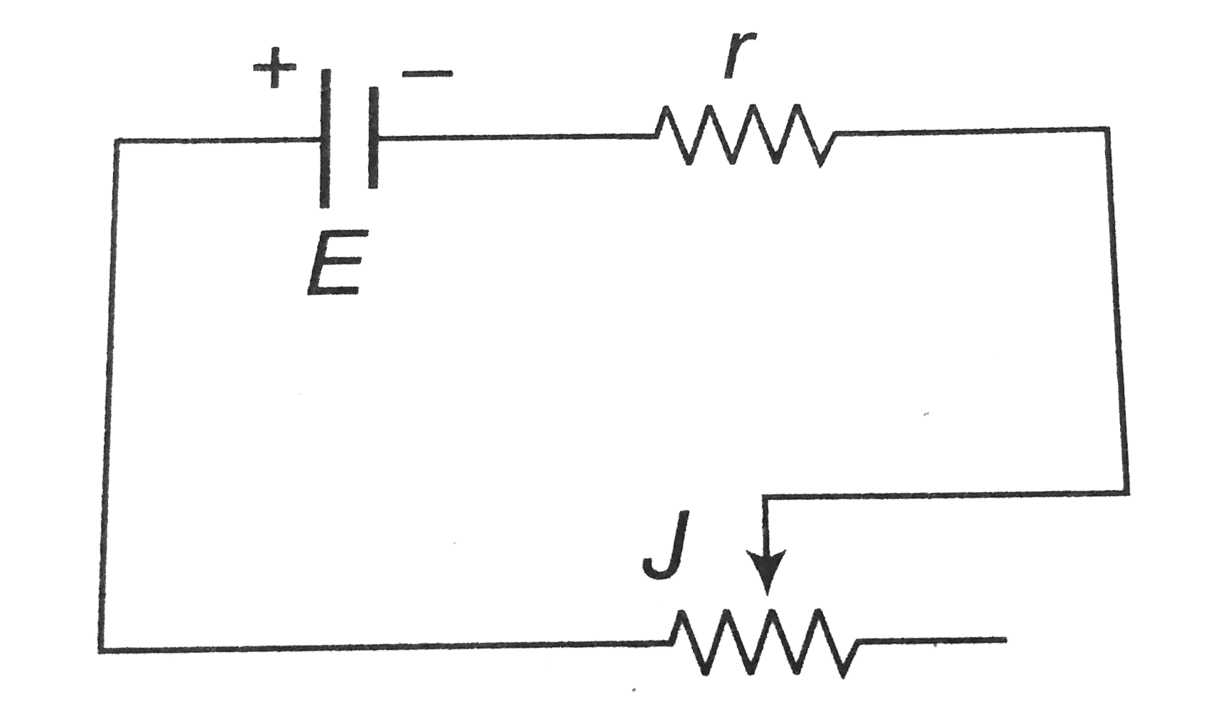
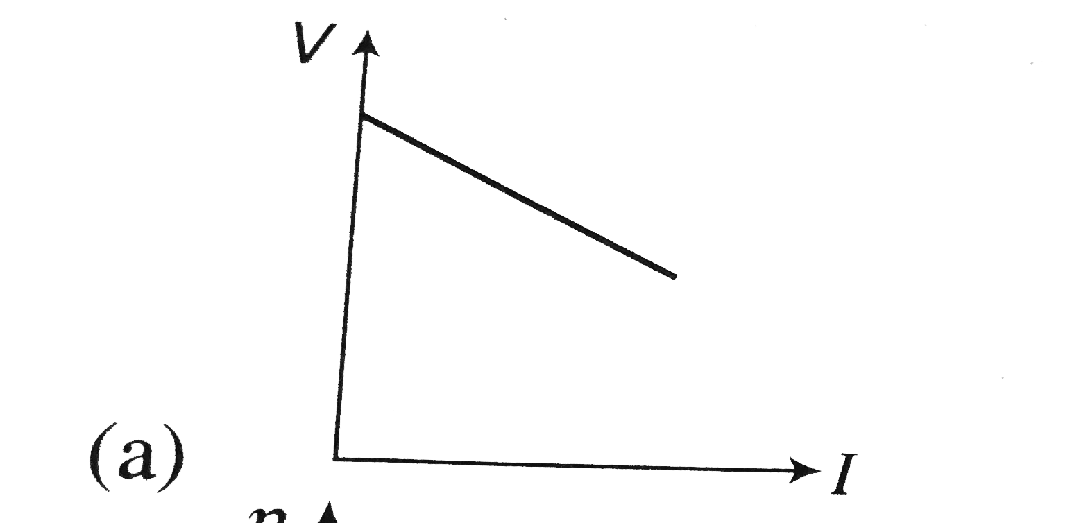
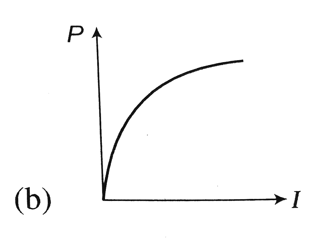
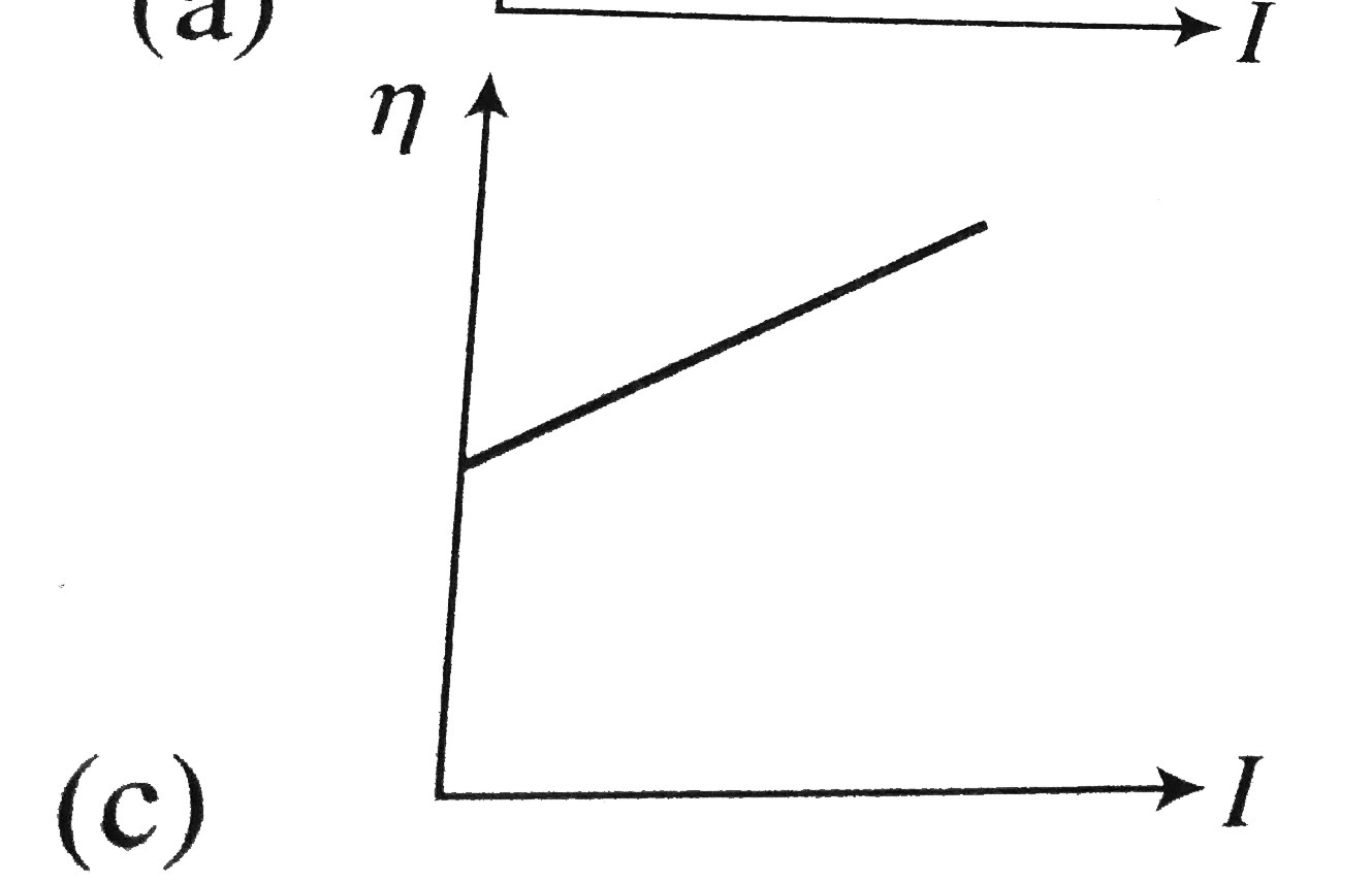
- Battery shown in figure has e.m.f. E and internal resistance r. Curren...
Text Solution
|