Home
Class 12
PHYSICS
Assertion : The switch S shown in the fi...

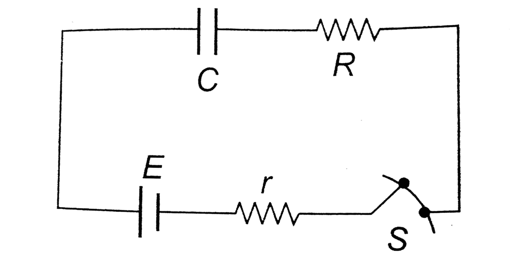
Assertion : The switch `S` shown in the figure is closed at `t = 0`. Initial current flowing through battery is `(E)/(R + r)`
Reason : Initially capacitor was uncharged, so resistance offered by capacitor at `t = 0` is zero

A

If both assertion and reason are ture and reason is the correct explanation of assertion.

B

If both assertion and reason are true but reason is not the correct explanation of assertion.

C

If assertion is true but reason is false.

D

If assertion and reason both are false.

Text Solution

Verified by Experts

The correct Answer is:
A

(a) Charge on capacitor `q = CE (1 - e^(-t//CR_(eq)))`
`:. I = (dq)/(dt) = (E)/(R_(eq)) e^(-t//CR)`
at `t = 0`
`I = (E)/(R_(eq)) = (E)/(R + r) implies` Resistance offered by capacitor is zero.
Promotional Banner

Topper's Solved these Questions

  • CURRENT ELECTRICITY

    A2Z|Exercise AIPMTNEET Questions|81 Videos
  • CURRENT ELECTRICITY

    A2Z|Exercise Section - C|1 Videos
  • CURRENT ELECTRICITY

    A2Z|Exercise Section - A|1 Videos
  • ATOMIC PHYSICS

    A2Z|Exercise Section D - Chapter End Test|30 Videos
  • DUAL NATURE OF RADIATION AND MATTER

    A2Z|Exercise Section D - Chapter End Test|30 Videos

Similar Questions

Explore conceptually related problems

The switch shown in figure is closed at t=0 find the charge throuh battery till time t=(L)/(R)

Charge flow through the battery after closing the switch is (initially all capacitors are unxharged) :

In the circuit shown, the switch 'S' is closed at t = 0 . Then the current through the battery steady state reached is

In the circuit shown in figure switch S is closed at time t=0 Current I from the battery at time t is given by

The switch S of the circuit is closed at t = 0. Find the current (in Amp.) through the capacitor when the switch S is closed at t = 0

In the circuit shown in figure-3.240 switch S is closed at time t=0. find the current through different wires and charge stored on the capacitor at any time t.

For the circuit shown in figure below, At t = 0, switch is closed, the initial current through resistor and final charge on capacitor are

In the circuit shown key is closed at t=0 with capacitor initially uncharged.

The current through the battery just after the switch S is Closed is (the capacitors are initially uncharged )

Knowledge Check

  • The switch shown in figure is closed at t=0 find the charge throuh battery till time t=(L)/(R)

    A
    `(L_(epsilon))/(eR^(2))`
    B
    `(L_(epsilon))/(2eR^(2))`
    C
    `(2L_(epsilon))/(eR^(2))`
    D
    None
  • In the circuit shown, the switch 'S' is closed at t = 0 . Then the current through the battery steady state reached is

    A
    `2 A`
    B
    `4A`
    C
    `6A`
    D
    `8A`
  • In the circuit shown in figure switch S is closed at time t=0 Current I from the battery at time t is given by

    A
    `3(1-e^(-2t))`
    B
    `3+e^(-2t))`
    C
    `3(1-e^(-t/9))
    D
    `3-e^(-2t)`
  • A2Z-CURRENT ELECTRICITY-Section B - Assertion Reasoning
    1. Assertion : The switch S shown in the figure is closed at t = 0. Initi...

      Text Solution

      |

    2. Assertion : Consider the two situations shown in the figure. Potential...

      Text Solution

      |

    3. Assertion : Electric field outside the conducting wire which carreis a...

      Text Solution

      |

    4. Assertion : When current through a bulb is increased by 2% power incre...

      Text Solution

      |

    5. Assertion : When the length of a conductor is doubled, its resistance ...

      Text Solution

      |

    6. Assertion : In the following circuit e.m.f. is 2 V internal resistance...

      Text Solution

      |

    7. Assertion : The e.m.f. of the drivercell in the potentiometer experime...

      Text Solution

      |

    8. Assertion : Direction of current can't be from negative potential Re...

      Text Solution

      |

    9. Statement I: Internal resistance of a battery is drawn parallel to a ...

      Text Solution

      |

    10. Assertion : When a cell is charged by connecting its positive terminal...

      Text Solution

      |

    11. Assertion : Potential measured by a voltmeter across a wire a always l...

      Text Solution

      |

    12. Assertion : The drift velocity of electrons in a metallic wire will de...

      Text Solution

      |

    13. Assertion : In meter bridge experiment, a high resistance is always co...

      Text Solution

      |

    14. Assertion : Insulators do no allow flow of current through them. Rea...

      Text Solution

      |

    15. Assertion : There is no current in the metals in the absence of electr...

      Text Solution

      |

    16. Assertion : The drift velocity of electrons in a metallic wire will de...

      Text Solution

      |

    17. Assertion : Electric field outside the conducting wire accurate measur...

      Text Solution

      |

    18. Assertion : A potentiometer of longer length is used of accurate measu...

      Text Solution

      |

    19. Assertion : The e.m.f. of the driver cell in the potentiometer experim...

      Text Solution

      |

    20. Assertion : A person touching a high power line gas stuck with the lin...

      Text Solution

      |