A
B
C
D
Text Solution
Verified by Experts
The correct Answer is:


Topper's Solved these Questions
ELECTROMAGNETIC INDUCTION
A2Z|Exercise Applications Of Emi|58 VideosELECTROMAGNETIC INDUCTION
A2Z|Exercise Problems On Mixed Concepts|37 VideosELECTROMAGNETIC INDUCTION
A2Z|Exercise Motional And Rotational Emf|95 VideosELECTRIC POTENTIAL & CAPACITANCE
A2Z|Exercise Section D - Chapter End Test|29 VideosELECTROMAGNETIC WAVES AND COMMUNICATION SYSTEM
A2Z|Exercise Section D - Chapter End Test|30 Videos
Similar Questions
Explore conceptually related problems
A2Z-ELECTROMAGNETIC INDUCTION-Inductor Circuits
- In the figure magnetic energy stored in the coil is
Text Solution
|
- A LC circuit is in the state of resonance. If C=0.1muF and L=0.25 henr...
Text Solution
|
- An oscillator circuit consists of an inductance of 0.5mH and a capacit...
Text Solution
|
- A coil of inductance 300mH and resistance 2 Omega. The current reaches...
Text Solution
|
- In series with 20 ohm resitor a 5 henry inductor is placed. To the com...
Text Solution
|
- A50 volt potential difference is suddenly applied to a coil with L=5xx...
Text Solution
|
- The current in a LR circuit builds up to (3)/(4th) of its steady state...
Text Solution
|
- In the circuit shown in figure switch S is closed at time t=0. The cha...
Text Solution
|
- The resistance in the following circuit is increase at a particle inst...
Text Solution
|
- In the current shown Fig., X is joined to Y for a long time and then X...
Text Solution
|
- In the circuit shown, the cell is deal. The coil has an inductance of ...
Text Solution
|
- The figure shows three circuit with identical batteries, inductors, an...
Text Solution
|
- In which of the following circuits is the current maximum just after t...
Text Solution
|
- An e.m.f. of 15 volt is applied in a circuit containing 5 henry induct...
Text Solution
|
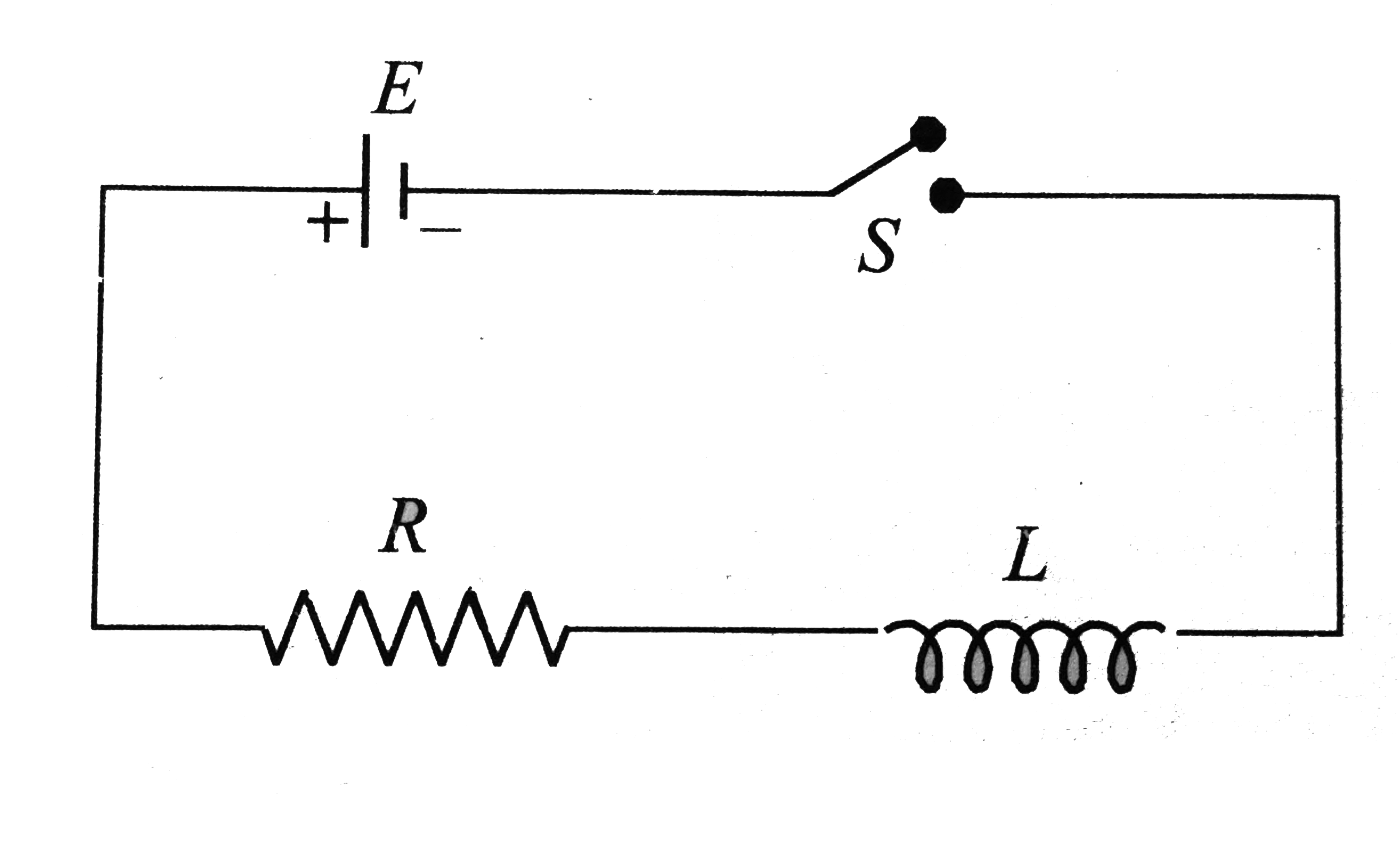
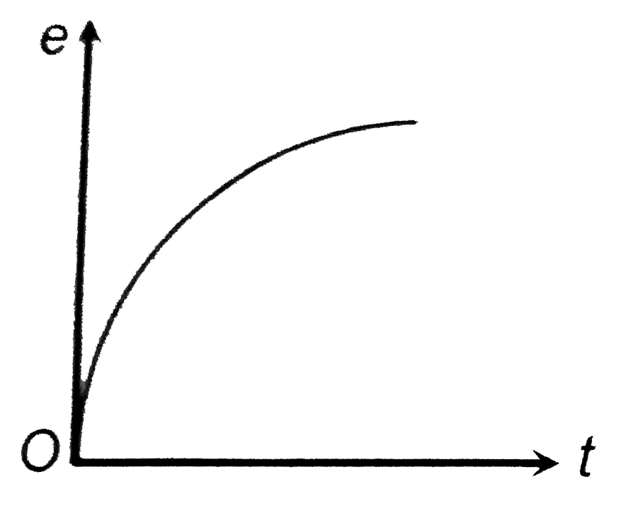
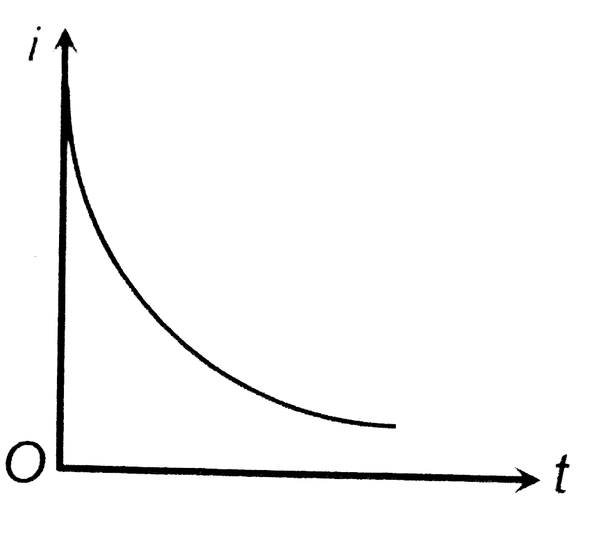
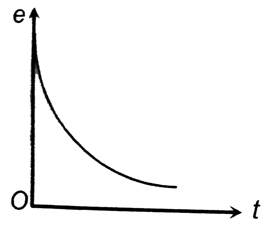
- Switch S of the circuit shows in Fig. is closed at t = 0. If e denotes...
Text Solution
|
- In the given circuit, let i(1) be the current drawn battery at time t=...
Text Solution
|
- In the circuit shown in Fig. Sliding contact is moving with uniform ve...
Text Solution
|
- Consider the circuit shown in figure. The current through the battery ...
Text Solution
|
- in the previous question, suppose the switch is again opened at t=0, t...
Text Solution
|
- In the circuit shown in figure switch S is closed at time t=0. The cha...
Text Solution
|