Home
Class 12
PHYSICS
The graphs given below depict the depend...

The graphs given below depict the dependence of two reactive impedances `X_(1)` and `X_(2)` on the frequency of the alternating e.m.f. applied individually to them. We can then say that

A

`X_(1)` is an inductor and `X_(2)` is a capacitor

B

`X_(1)` is an resistor and `X_(2)` is a capacitor

C

`X_(1)` is an capacitor and `X_(2)` is ainductor

D

`X_(1)` is an inductor and `X_(2)` is a resistor

Text Solution

Verified by Experts

The correct Answer is:
C

We have `X_(C)=1/(Cxx2pif)` and `X_(L)=Lxx2pif`
Promotional Banner

Topper's Solved these Questions

  • ALTERNATING CURRENT

    A2Z|Exercise Different Ac Circuits|30 Videos
  • ALTERNATING CURRENT

    A2Z|Exercise Power In Ac Circuits|21 Videos
  • ALTERNATING CURRENT

    A2Z|Exercise Section D - Chapter End Test|30 Videos
  • ATOMIC PHYSICS

    A2Z|Exercise Section D - Chapter End Test|30 Videos

Similar Questions

Explore conceptually related problems

The graph of f(x) is given below. Then, (a) Graph of -f(x)+2 is

Figures (i) and (ii) below show the displacement-time graphs of two particles moving along the x -axis. We can say that

The graph of y = f(x) is given below then the graph y = |f(|x|)| is :

If the frequency of alternating e.m.f. is in L-C-R circuit, then the value of impedance Z will change with log (frequency) as

Students A and B connect the two resistors R_(1) and R_(2) given to them in the manners shown below : and then insert them at X and Y into the measuring circuit shown below : We can then say that

The graphs shown in Fig. represent the variation of opposition offered by the circuit element of the flow of a.c. with frequency of applied e.m.f. Iddntify the circuit element .

Given below is graph of y = f(x) then

The graph of y=f(x) is given below then the graph of y=If((xl)] is : 1/4 (D) none of these

A2Z-ALTERNATING CURRENT-Connected With Ac
  1. The reactance of a coil when used in the domestic AC power supply (220...

    Text Solution

    |

  2. The figure represents the voltage applied across a pure inductor. The ...

    Text Solution

    |

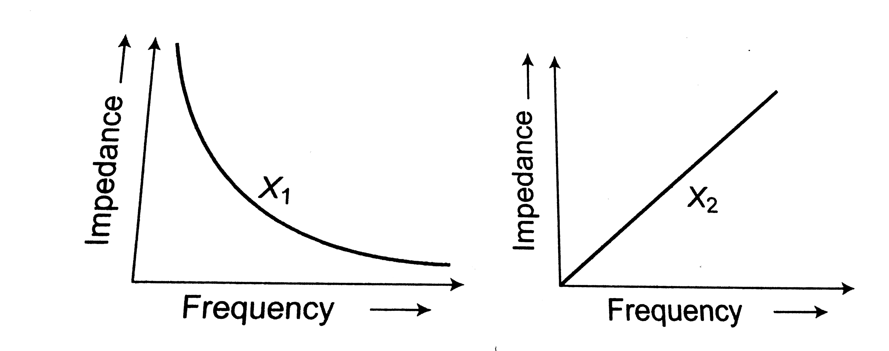
  3. The graphs given below depict the dependence of two reactive impedance...

    Text Solution

    |

  4. Identify the graph which correctly represents the variation of capacit...

    Text Solution

    |

  5. A resistance of 40 ohms and an inductance of 95.5 millihenry are conne...

    Text Solution

    |

  6. For high frequency, a capacitor offers

    Text Solution

    |

  7. Reactance of an inductor of 1/(pi) henry at 50Hz frequency is

    Text Solution

    |

  8. The resistance of a coil for DC is in ohms. In AC, the resistance

    Text Solution

    |

  9. An alternating current of frequency 'f' is flowing in a circuit contai...

    Text Solution

    |

  10. An inductance of 1mH a condenser of 0.5 henry and capacitance of 10xx1...

    Text Solution

    |

  11. If resistance of 100Omega , inductance of 0.5 henry and capacitor of 1...

    Text Solution

    |

  12. An inductive circuit a resistance of 10ohm and an inductance of 2.0 h...

    Text Solution

    |

  13. An inductive circuit a resistance of 10ohm and an inductance of 2.0 h...

    Text Solution

    |

  14. Same current is flowing in two alternating circuits. The first circuit...

    Text Solution

    |

  15. In a series circuit R=300Omega, L=0.9H, C=2.0 muF and omega=1000rad//s...

    Text Solution

    |

  16. In a L-R circuit, the value of L is (0.4/(pi)) henry and the value of ...

    Text Solution

    |

  17. An e.m.f. E=4cos(1000t)volt is applied to an LR circuit of inductance ...

    Text Solution

    |

  18. In an AC circuit, a resistance of Rohm is connected is series with an ...

    Text Solution

    |

  19. If an 8Omega resistance and 6Omega reactance are present in an AC seri...

    Text Solution

    |

  20. A 220V,50Hz Ac source is connected to an inductance of 0.2H and a resi...

    Text Solution

    |