Home
Class 12
PHYSICS
A 500 Omega resistor and a capacitor C a...

A `500 Omega` resistor and a capacitor `C` are connected in series across `50 Hz AC` supply mains. The r.m.s potential difference recorded on voltmeter `V_(1)` and `V_(2)` are `V_(1)=120 V` and `V_(2)=160 V`. The power taken for the mains is:

A

`480 W`

B

`240 W`

C

`28.8 W`

D

`14.4 W`

Text Solution

Verified by Experts

The correct Answer is:
C

`V_(r.m.s)sqrt(V_(1)^(2)+V_(2)^(2))=sqrt(120^(2)+160^(2))`
`I_(V)xx500=120, I_(V)=24A`
`P_(av)=I_(V)^(2)R`
Promotional Banner

Topper's Solved these Questions

  • ALTERNATING CURRENT

    A2Z|Exercise Section B - Assertion Reasoning|26 Videos
  • ALTERNATING CURRENT

    A2Z|Exercise AIPMT/NEET Questions|31 Videos
  • ALTERNATING CURRENT

    A2Z|Exercise Power In Ac Circuits|21 Videos
  • ATOMIC PHYSICS

    A2Z|Exercise Section D - Chapter End Test|30 Videos

Similar Questions

Explore conceptually related problems

A 0.2 k Omega resistor and 15 mu F capacitor are connected in series to a 220 V, 50 Hz ac source. The impadance of the circuit is

A resistor R and the capacitor C are connected in series across an ac source of rms voltage 5V if the rms voltage across C is 3V then that across R is .

A 80 Omega resistor a 2 H inductor and a 5.07xx10^(-6) F capacitor are connected in series to an AC power supply of 220 V, 50 Hz. Calculate the potential difference across the resistor.

A 10muF capacitor is connected across a 200V , 50Hz A.C. supply. The peak current through the circuit is

An electrical heater and a capacitor are joined in series across a 220V, 50Hz, AC supply. The potential difference across the heater is 90V . The potential difference across the capacitor will be about:

Two capacitors C_(1) and C_(2) are connected in a circuit as shown in figure. The potential difference (V_(A) - V_(B)) is

4 bulbs marked 40 W , 250 V are connected in series with 250 V mains. The total power is

In a R-L-C series circuit shown in readings of voltmeters V_1 and V_2 are 100V and 120 V . Choose the corredct statement(s). .

A resistor and a capacitor are connected in series with an a.c. source. If the potential drop across the capacitor is 5 V and that across resistor is 12 V, applied voltage is

A2Z-ALTERNATING CURRENT-Problems Based On Mixed Concepts
  1. A coil of inductance 0.1 H is connected to 50 V, 100Hz generator and c...

    Text Solution

    |

  2. A dc ammeter and a hot wire ammeter are connected to a circuit in seri...

    Text Solution

    |

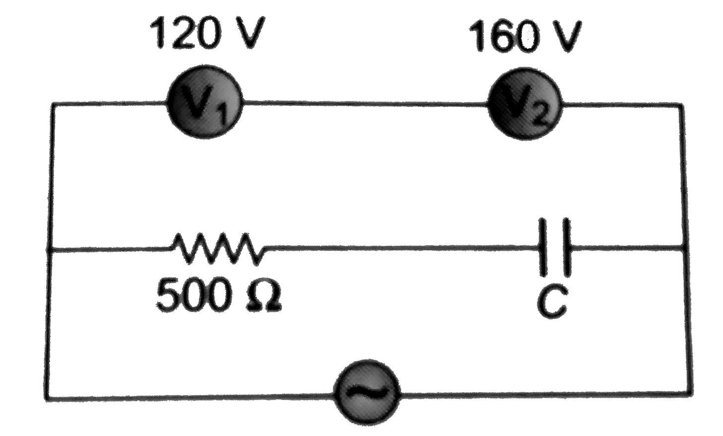
  3. A 500 Omega resistor and a capacitor C are connected in series across ...

    Text Solution

    |

  4. Two resistor are connected in series across a 5 V rms source of altern...

    Text Solution

    |

  5. A coil has an inductance of 0.7 H and is joined in series with a resis...

    Text Solution

    |

  6. In the circuit shown in figure when the frequency of oscillator is inc...

    Text Solution

    |

  7. In the figure shown, three AC voltmeters have been connected. At reson...

    Text Solution

    |

  8. An inductor L, a capacitor C and AC ammeters A(1),A(2) and A(3) are co...

    Text Solution

    |

  9. In the circuit shown, R is a pure resistor, L is an inductor of neglig...

    Text Solution

    |

  10. A typical light dimmer used to dim the stage lights in a theater consi...

    Text Solution

    |

  11. If the instantaneous current in a circuit is given by i=2cos (omegat-p...

    Text Solution

    |

  12. A coil has an inductance of 0.7 H and is joined in series with a resis...

    Text Solution

    |

  13. In a region of uniform magnetic inductance B=10^(-2)tesla. A circular ...

    Text Solution

    |

  14. In the circuit shown in fig. if both the bulbs (B1) and (B2) are ident...

    Text Solution

    |

  15. In a region of uniform magnetic inductance B=10^(-2)tesla. A circular ...

    Text Solution

    |

  16. In the circuit given below, what will be the reading of the voltmeter?

    Text Solution

    |

  17. In the circuit shown below, what will be the reading of the voltmeter ...

    Text Solution

    |

  18. The diagram shows a capacitor C and a resistor R connected in series t...

    Text Solution

    |

  19. In the circuit shown in figure neglecting source resistance the voltme...

    Text Solution

    |

  20. In the circuit shown in figureure the AC source gives a voltage V=20co...

    Text Solution

    |