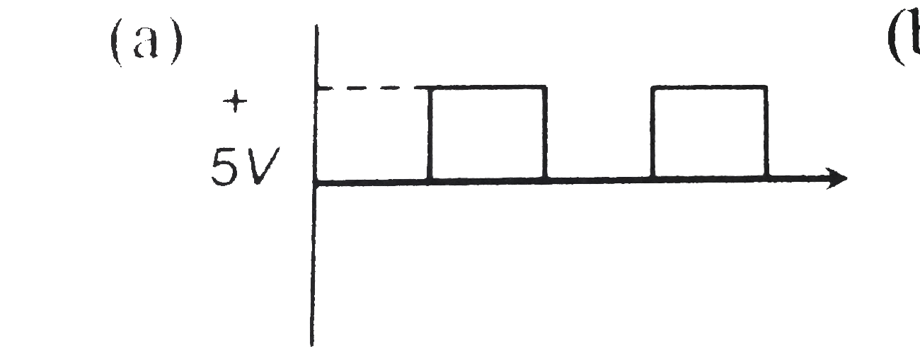
A
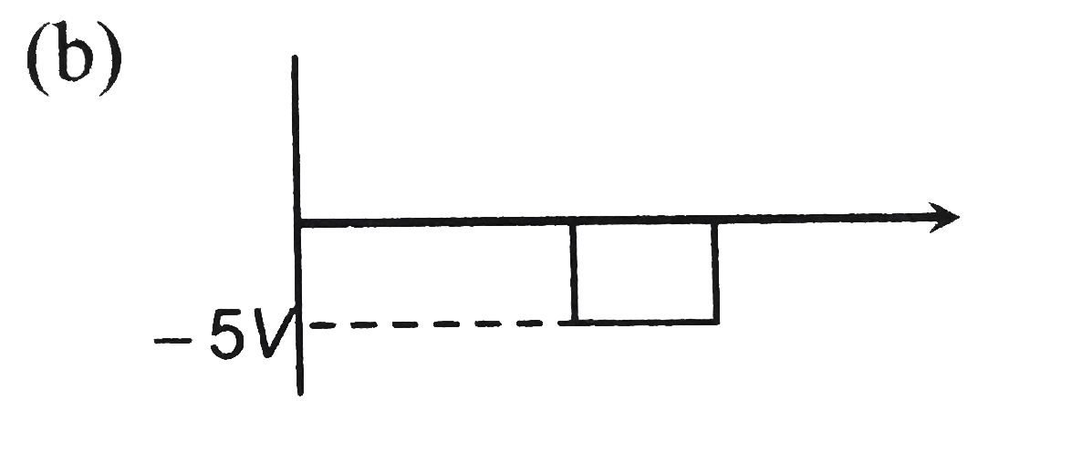
B
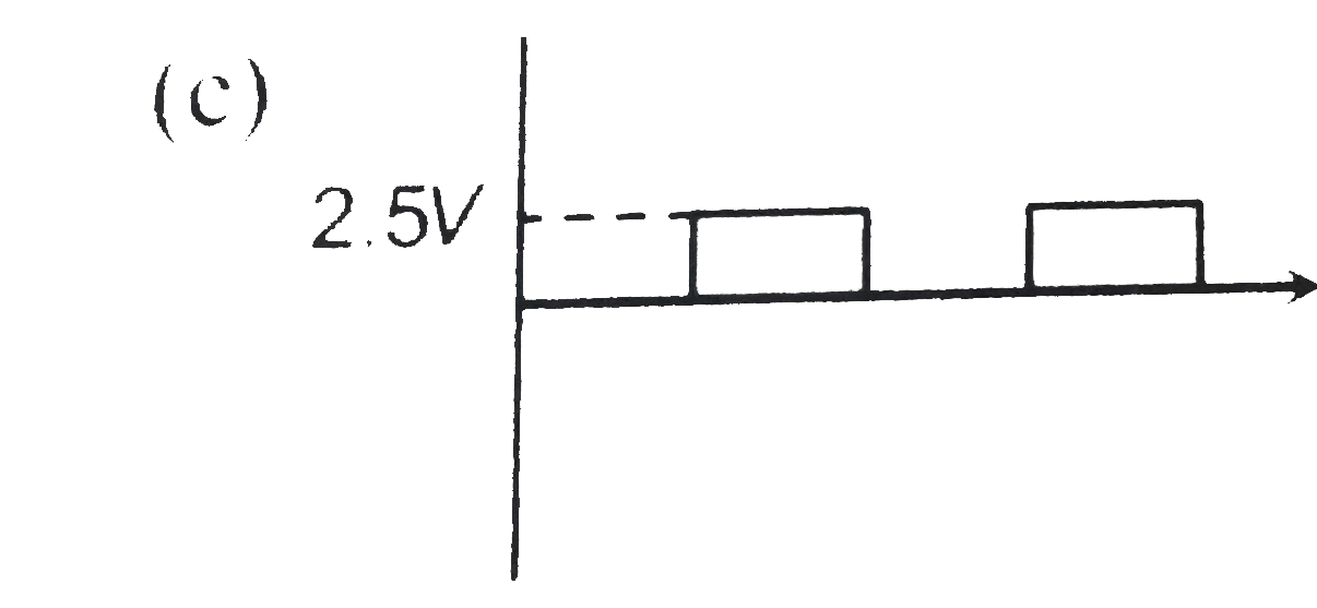
C
D
Text Solution
Verified by Experts
The correct Answer is:


Topper's Solved these Questions
SEMICONDUCTOR ELECTRONICS
A2Z|Exercise Junction Transistor|47 VideosSEMICONDUCTOR ELECTRONICS
A2Z|Exercise Digital Electronics|40 VideosSEMICONDUCTOR ELECTRONICS
A2Z|Exercise Junction Diode|57 VideosNUCLEAR PHYSICS
A2Z|Exercise Section D - Chapter End Test|29 VideosSOURCE AND EFFECT OF MAGNETIC FIELD
A2Z|Exercise Section D - Chapter End Test|30 Videos
Similar Questions
Explore conceptually related problems
A2Z-SEMICONDUCTOR ELECTRONICS-Diode In Circuits
- In the circuit, if the forward voltage drop for the diode is 0.5 V, th...
Text Solution
|
- Current in the circuit will be
Text Solution
|
- The diode used in the circuit shown in the figure has a constant volta...
Text Solution
|
- A sinusoidal voltage of peak value 200 volts is connected to a diode a...
Text Solution
|
- The junction diode in the following circuit requires a minimum current...
Text Solution
|
- In the circuit given below, V(t) is the sinusoidal voltage source, vol...
Text Solution
|
- The peak voltage in the output of a half-wave diode rectifier fed with...
Text Solution
|
- In the following circuits PN-junction diodes D(1), D(2) and D(3) are i...
Text Solution
|
- The circuit shown in following figure contains two diode D(1) and D(2)...
Text Solution
|
- Find V(AB)
Text Solution
|
- A diode is connected to 220V (rms) ac in series with a capacitor as sh...
Text Solution
|
- In the circuit shown in figure the maximum output voltage V(0) is
Text Solution
|
- In the following circuit find I(1) and I(2)
Text Solution
|
- Ge and Si diodes conduct at 0.3 V and 0.7 V respectively. In the follo...
Text Solution
|
- In the following circuit I(1) and I(2) are respectively
Text Solution
|
- In space charge limited region, the plate current in a diode is 10 mA ...
Text Solution
|
- When a silicon PN junction is in forwards biased condition with series...
Text Solution
|
- In the following circuit the equivalent resistance between A and B is
Text Solution
|
- In the following circuit of PN junction diodes D(1),D(2) and D(3) are ...
Text Solution
|
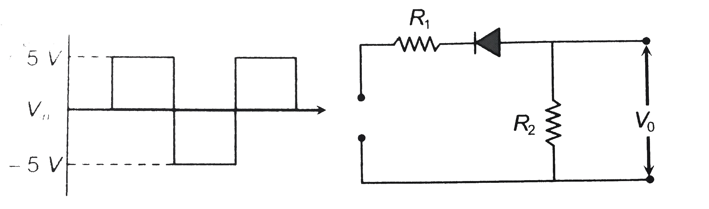
- A waveform shown when applied to the following circuit will produce wh...
Text Solution
|