A
B
C
D
Text Solution
Verified by Experts
The correct Answer is:


Topper's Solved these Questions
SEMICONDUCTOR ELECTRONICS
A2Z|Exercise Section B - Assertion Reasoning|22 VideosSEMICONDUCTOR ELECTRONICS
A2Z|Exercise AIPMT/NEET Questions|77 VideosSEMICONDUCTOR ELECTRONICS
A2Z|Exercise Digital Electronics|40 VideosNUCLEAR PHYSICS
A2Z|Exercise Section D - Chapter End Test|29 VideosSOURCE AND EFFECT OF MAGNETIC FIELD
A2Z|Exercise Section D - Chapter End Test|30 Videos
Similar Questions
Explore conceptually related problems
A2Z-SEMICONDUCTOR ELECTRONICS-Problems Based On Mixed Concepts
- In the circuit of figure. Treat the diodes as ideal. Current in the 4 ...
Text Solution
|
- The potential barrier developed in the diode of figure is 0.5 V. The c...
Text Solution
|
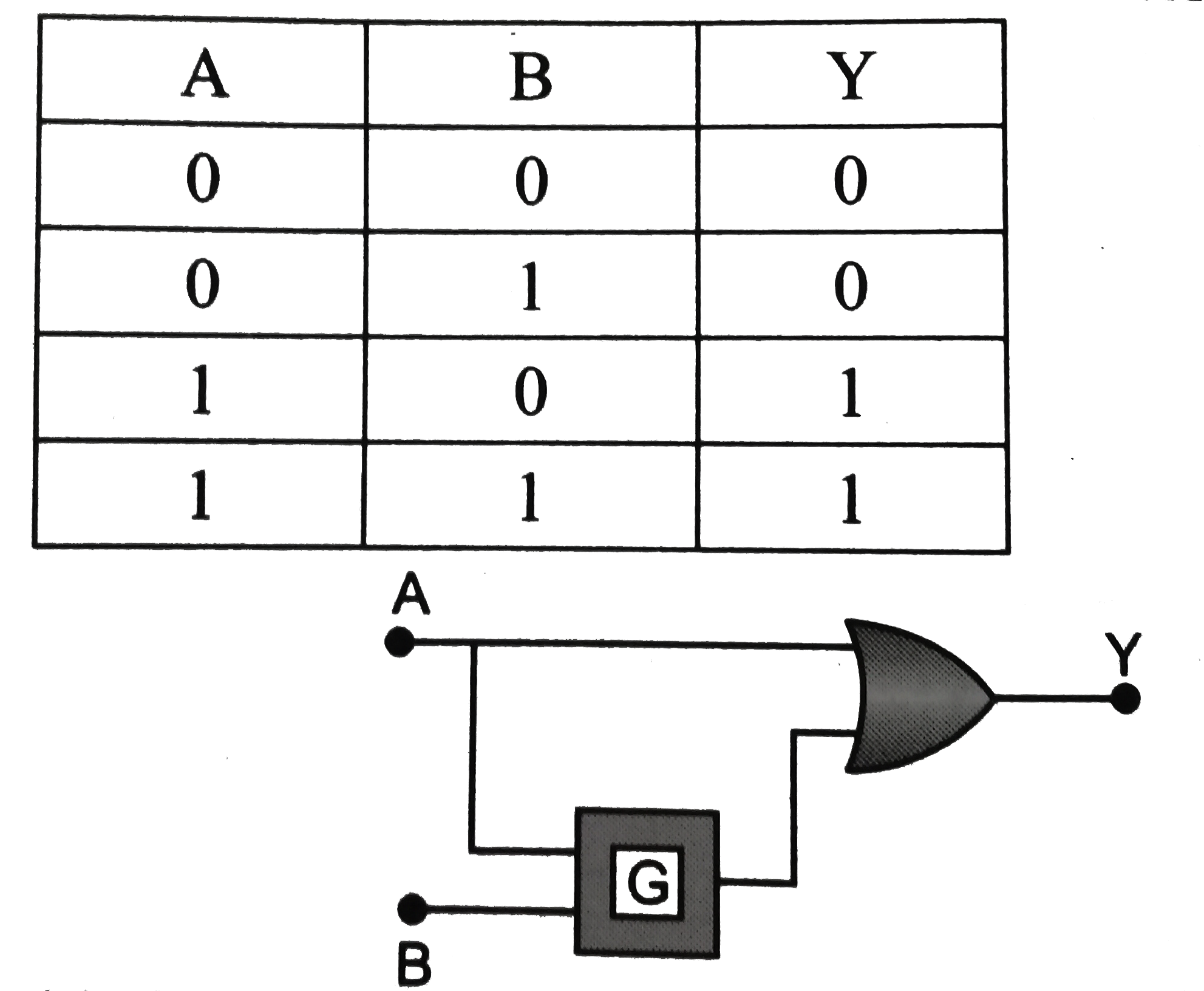
- Identify the logic gate G in the combination of gates shown in fig. Th...
Text Solution
|
- The current amplification of the common base NPN transistor is 0.96. W...
Text Solution
|
- In figure the current supplied by the battery is
Text Solution
|
- Figure shows a piece of semiconductor (pure one) S in series with a va...
Text Solution
|
- A semiconductor diode and a resistor of constant resistance are connec...
Text Solution
|
- A transistor is used in a common-emitter mode in an amplifier circuit....
Text Solution
|
- A transistor is used in common-emitter mode in an amplifier circuit. W...
Text Solution
|
- A transistor is used in common-emitter mode in an amplifier circuit. W...
Text Solution
|
- In a common emitter amplifier, using output reisistance of 5000 ohm an...
Text Solution
|
- In a common emitter amplifier, using output reisistance of 5000 ohm an...
Text Solution
|
- A sinusiodal voltage of rms value 200 volt is connected to the diode a...
Text Solution
|
- In the circuit shown, the base current is 30muA. The value of R(1) is
Text Solution
|
- The diagram shows a logic network. If the inputs L,M and N are al...
Text Solution
|
- In the circuit shown in the diagram, the operational amplifier may be ...
Text Solution
|
- An input voltage V(i) of 0.20 V is applied to an operational amplifier...
Text Solution
|
- The function of a half -adder may be represented as shown in Figure. ...
Text Solution
|
- The diagram shows an operational circuit. Which of the following corre...
Text Solution
|
- A digital system comprises a HAND gate with a NOT gate on each of its ...
Text Solution
|