A
B
C
D
Text Solution
Verified by Experts
The correct Answer is:


Topper's Solved these Questions
SEMICONDUCTOR ELECTRONICS
A2Z|Exercise Section B - Assertion Reasoning|22 VideosSEMICONDUCTOR ELECTRONICS
A2Z|Exercise AIPMT/NEET Questions|77 VideosSEMICONDUCTOR ELECTRONICS
A2Z|Exercise Digital Electronics|40 VideosNUCLEAR PHYSICS
A2Z|Exercise Section D - Chapter End Test|29 VideosSOURCE AND EFFECT OF MAGNETIC FIELD
A2Z|Exercise Section D - Chapter End Test|30 Videos
Similar Questions
Explore conceptually related problems
A2Z-SEMICONDUCTOR ELECTRONICS-Problems Based On Mixed Concepts
- A sinusiodal voltage of rms value 200 volt is connected to the diode a...
Text Solution
|
- In the circuit shown, the base current is 30muA. The value of R(1) is
Text Solution
|
- The diagram shows a logic network. If the inputs L,M and N are al...
Text Solution
|
- In the circuit shown in the diagram, the operational amplifier may be ...
Text Solution
|
- An input voltage V(i) of 0.20 V is applied to an operational amplifier...
Text Solution
|
- The function of a half -adder may be represented as shown in Figure. ...
Text Solution
|
- The diagram shows an operational circuit. Which of the following corre...
Text Solution
|
- A digital system comprises a HAND gate with a NOT gate on each of its ...
Text Solution
|
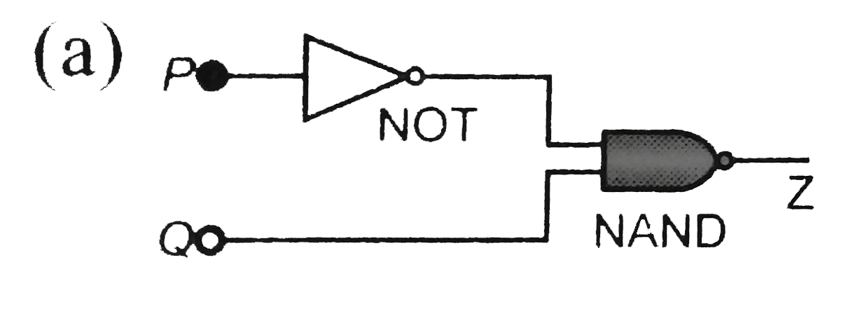
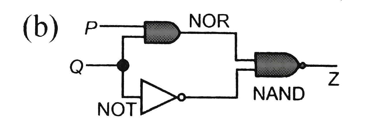
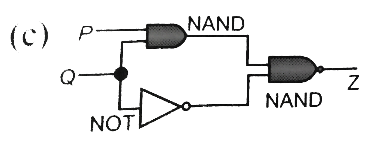
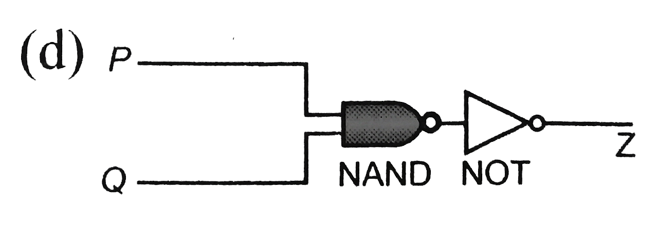
- A combination of logic gates has the truth table below |(P,Q,Z),(0,0...
Text Solution
|
- Identify the gate in figure.
Text Solution
|
- What is the output in the given figure?
Text Solution
|
- The diagram shows a logic network. Which single gate is equivalen...
Text Solution
|
- For the given combination of gates, if the logic states of inputs A,B,...
Text Solution
|
- Figure shows a combination of logic gates. To what single gate is thi...
Text Solution
|
- Logic gates X and Y have the truth tables shown below |(P,Q,R,P,R...
Text Solution
|
- Figure shows a circuit designed to control a lamp. For what positions ...
Text Solution
|
- The typical ionisation energy of a donor in silicon is
Text Solution
|
- In PN-junction diode the reverse saturation curren is 10^(-5) amp at 2...
Text Solution
|
- A potential difference of 2V is applied between the opposite faces of ...
Text Solution
|
- The contribution in the total current flowing through a semiconductor ...
Text Solution
|