A
B
C
D
Text Solution
Verified by Experts
The correct Answer is:


Topper's Solved these Questions
SEMICONDUCTOR ELECTRONICS
A2Z|Exercise AIIMS Questions|38 VideosSEMICONDUCTOR ELECTRONICS
A2Z|Exercise Assertion Reason|18 VideosSEMICONDUCTOR ELECTRONICS
A2Z|Exercise Section B - Assertion Reasoning|22 VideosNUCLEAR PHYSICS
A2Z|Exercise Section D - Chapter End Test|29 VideosSOURCE AND EFFECT OF MAGNETIC FIELD
A2Z|Exercise Section D - Chapter End Test|30 Videos
Similar Questions
Explore conceptually related problems
A2Z-SEMICONDUCTOR ELECTRONICS-AIPMT/NEET Questions
- In a n-type semiconductor, which of the following statement is true?
Text Solution
|
- In a common emitter (CE) amplifier having a voltage gain G, the transi...
Text Solution
|
- The output (X) of the logic circuit shown in figure will be
Text Solution
|
- The given graph represents V-I characterstic for a semiconductor devic...
Text Solution
|
- The barrier potential of a p-n-junction depends on (i) Type of sem...
Text Solution
|
- Which logic gate is represented by the following combination of logic ...
Text Solution
|
- If an a p-njunction, a square input signal of 10V is applied, as shown...
Text Solution
|
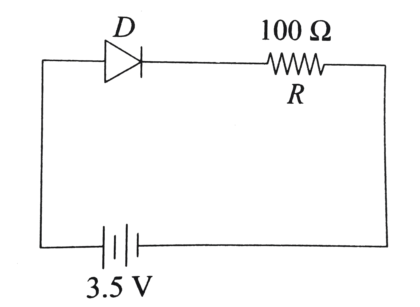
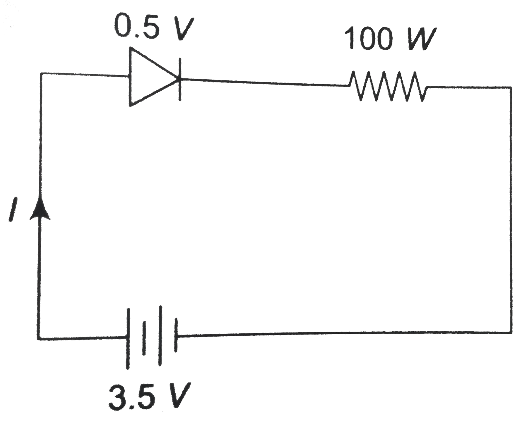
- In the given figure, a diode D is connected to an external resistance ...
Text Solution
|
- Consider the junction diode as ideal. The value of current flowing thr...
Text Solution
|
- A npn transistor is connected in common emitter configuration in a giv...
Text Solution
|
- To get output 1for the following circuit, the correct choice for the i...
Text Solution
|
- For CE transistor amlifier, the audio signal voltage across the colle...
Text Solution
|
- The given circuit has two ideal diodes connected as show in the figure...
Text Solution
|
- What is the output Y in the following circuit, when all the three outp...
Text Solution
|
- In a common emitter transistor amplifier the audio signal voltage acro...
Text Solution
|
- The given electrical network is equivalent to:
Text Solution
|
- Which of the following represents forward biase diode?
Text Solution
|
- In the combination of the following gates the output Y can be written ...
Text Solution
|
- In the circuit shown in the figure, the input voltage V(i) is 20V,V(BE...
Text Solution
|
- In a p-n junction diode, change in temperature due to heating
Text Solution
|