A
B
C
D
Text Solution
Verified by Experts
The correct Answer is:


Topper's Solved these Questions
SEMICONDUCTOR ELECTRONICS
A2Z|Exercise Assertion Reason|18 VideosSEMICONDUCTOR ELECTRONICS
A2Z|Exercise SECTION -D|1 VideosSEMICONDUCTOR ELECTRONICS
A2Z|Exercise AIPMT/NEET Questions|77 VideosNUCLEAR PHYSICS
A2Z|Exercise Section D - Chapter End Test|29 VideosSOURCE AND EFFECT OF MAGNETIC FIELD
A2Z|Exercise Section D - Chapter End Test|30 Videos
Similar Questions
Explore conceptually related problems
A2Z-SEMICONDUCTOR ELECTRONICS-AIIMS Questions
- In short wave communication waves of which of the following frequeunci...
Text Solution
|
- To a germanium sample, traces of gallium are added as an impurity. The...
Text Solution
|
- In the following common emitter configuration an NPN transistor with c...
Text Solution
|
- The maximum distance upto which TV transmission from a TV tower of...
Text Solution
|
- A Ge specimen is dopped with Al. The concentration of acceptor atoms i...
Text Solution
|
- Which logic gate is represented by the following combination of logic ...
Text Solution
|
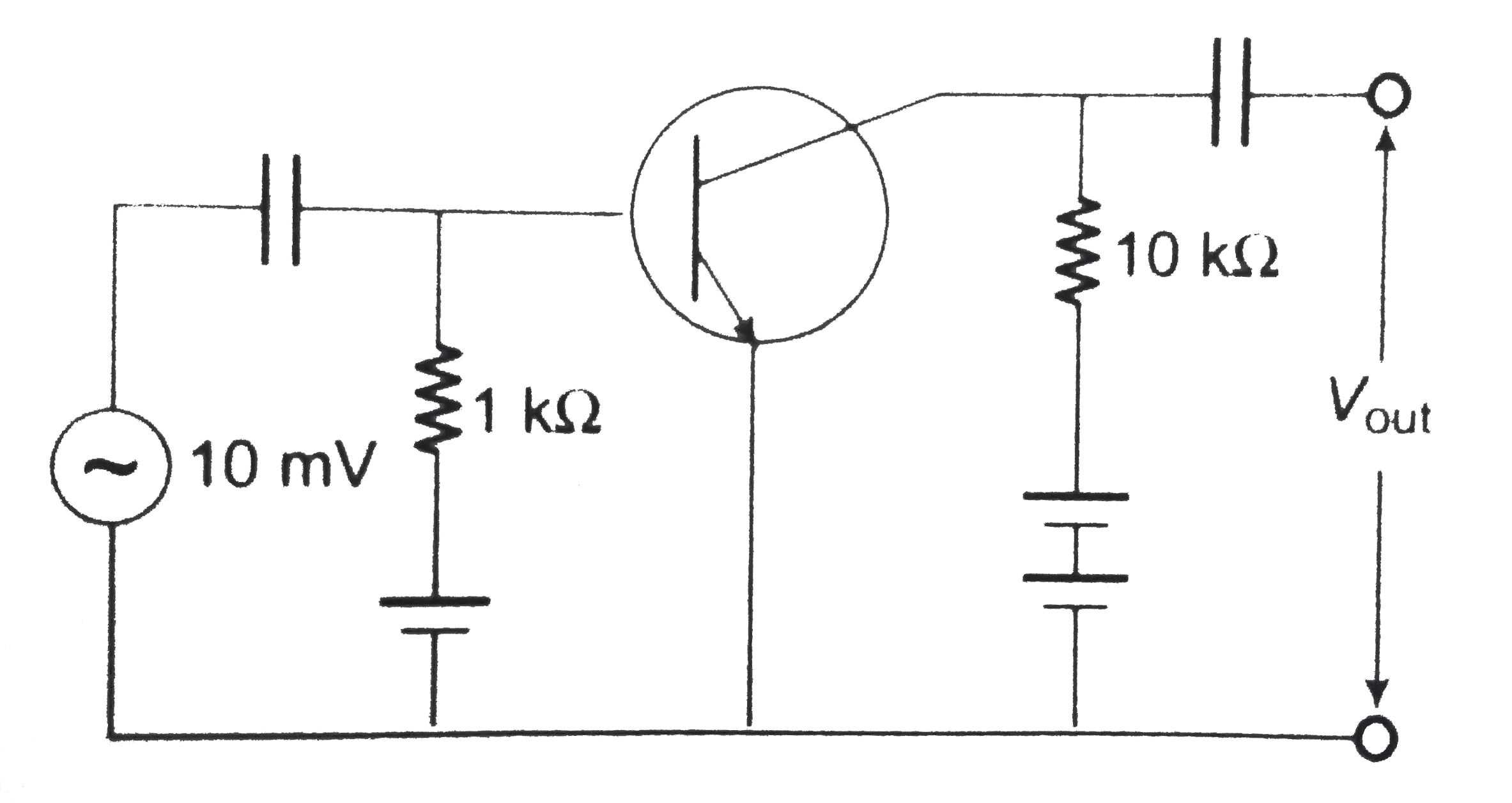
- The voltage gain of the following amplifier is
Text Solution
|
- Which of the following logic gates is an universal gate?
Text Solution
|
- Consider an n-p-n transistor amplifer in common-emitter configuration....
Text Solution
|
- In a semiconducting material the mobilities of electrons and holes are...
Text Solution
|
- The circuit shown below acts as
Text Solution
|
- For sky wave propagation of 10 MHz signal, what should be the minimum ...
Text Solution
|
- Reverse bias applied to a junction diode
Text Solution
|
- The circuit given below represents which of the logic operations?
Text Solution
|
- An amplifier has a voltage gain A(V)=1000. The voltage gain in dB is
Text Solution
|
- A light emitting diode (LED) has a voltage drop of 2V across it and pa...
Text Solution
|
- The minimum potential difference between the base and emitter required...
Text Solution
|
- If in a p-n junction diode , a square input single of 10 V is applied...
Text Solution
|
- The input resistance of a common emitter transistor amplifer, if the o...
Text Solution
|
- The combination of the gates shown in the figure below produces
Text Solution
|