Home
Class 12
PHYSICS
The diode shown in the circuit is a sili...

The diode shown in the circuit is a silicon diode. The potential difference between the points `A` and `B` will be

A

6 V

B

0.6 V

C

0. 7 V

D

0 V

Text Solution

Verified by Experts

The correct Answer is:
A

The diode is reverse biased. No current flows in the circuit.
`therefore` P.D. of 6 V acts across only the diode or between the points A and B.
Promotional Banner

Topper's Solved these Questions

  • ROTATIONAL MOTION

    MARVEL PUBLICATION|Exercise TEST YOUR GRASP - 3|8 Videos
  • STATIONARY WAVES

    MARVEL PUBLICATION|Exercise TEST YOUR GRASP-8|20 Videos

Similar Questions

Explore conceptually related problems

The potential difference between the points A and B in the given circuit is

In the given circuit, the potential difference between the points A and B is

In the circuit shown in figure-3.331, the potential difference between points A and Bis :

Potential difference between the points B and E of the circuit is -

In given circuit , the potential difference between points A and B is

In the circuit shown in figure potential difference between the points A and B in the steady state is

What is the potential difference between points A and B in the circuit shown?

In the circuit shown, the potential difference between A and B is:

For the circuit in find the potential difference between points a and b.

Find the potential difference (inV) between points A and B shown in the circuit.

MARVEL PUBLICATION-SEMICONDUCTORS -MCQs
  1. When forward bias is applied to a P-N junction, then what happence to ...

    Text Solution

    |

  2. In an unbiased p-n junction,

    Text Solution

    |

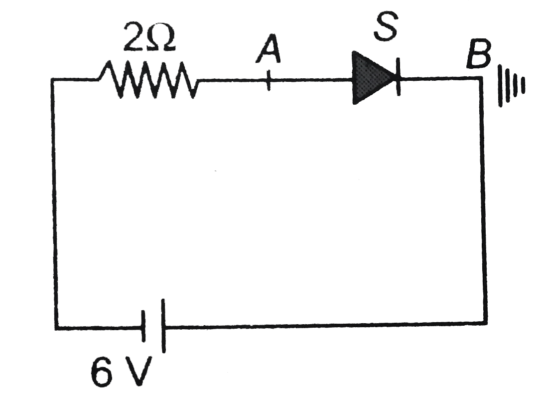
  3. The diode shown in the circuit is a silicon diode. The potential diffe...

    Text Solution

    |

  4. A diode having potential difference 0.5 V across its junction which do...

    Text Solution

    |

  5. In a reverse biased diode, when the applied voltage changes by 1V, the...

    Text Solution

    |

  6. Barrier potential of a p-n junction diode does not depend on

    Text Solution

    |

  7. When p-n junction diode is forward biased then

    Text Solution

    |

  8. If a full wave rectifier circuit is operating from 50 Hz mains, the fu...

    Text Solution

    |

  9. Application of a forward biase to a p-n junction:

    Text Solution

    |

  10. The barrier potential of a p-n-junction depends on (i) Type of sem...

    Text Solution

    |

  11. A recutifier is used to

    Text Solution

    |

  12. Freuency of given AC signal is 50 Hz. When it connected to a half - wa...

    Text Solution

    |

  13. The depletion layer in a p-n junction diode is 10^(-6) m wide and its ...

    Text Solution

    |

  14. A semiconducting device is connected is series with a battery, a resis...

    Text Solution

    |

  15. The dominant mechanisms for motion of charge carriers in forward and r...

    Text Solution

    |

  16. For the diode D, the forward resistance is zero and the backward resis...

    Text Solution

    |

  17. In the middle of the depletion layer of a reverse - biased p - n junc...

    Text Solution

    |

  18. Two PN-junction can be connected in series by three different methods ...

    Text Solution

    |

  19. In a p- n junction diode not connected to any circuit,

    Text Solution

    |

  20. The peak voltage in the output of a half-wave diode rectifier fed with...

    Text Solution

    |