A
B
C
D
Text Solution
Verified by Experts
The correct Answer is:


Topper's Solved these Questions
Similar Questions
Explore conceptually related problems
MARVEL PUBLICATION-SEMICONDUCTORS -MCQs
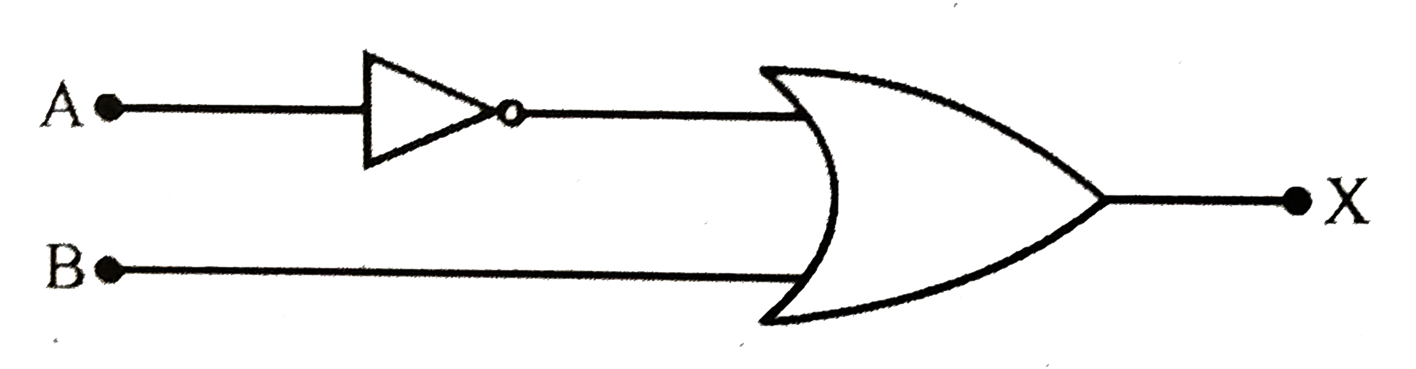
- What is the output X of the following logic gate circuit?
Text Solution
|
- What is the output X of the following logic gate circuit?
Text Solution
|
- What is the output X in the following logic gate circuit?
Text Solution
|
- In a chemical process, alarm systems are to be activated whenever eith...
Text Solution
|
- When the inputs of a two input logic gate are 0 and 0, the output is 1...
Text Solution
|
- The output of OR gate is 1
Text Solution
|
- Which logic gate produces LOW output when any of the inputs in HIGH
Text Solution
|
- If the Output of two NAND gates is given to input of a NAND gate. Then...
Text Solution
|
- In the circuit below, A and B represents two inputs and C represents t...
Text Solution
|
- For a NAND gate the inputs and outputs for different time invervals ar...
Text Solution
|
- The output y, when all three inputs are first high and then low, will ...
Text Solution
|
- In the following circuit, the output Y for all possible inputs A and B...
Text Solution
|
- The combination of the 'NAND' gates shown here (Fig.) and (ii)) are eq...
Text Solution
|
- The temperature (T) dependence of resistivity (rho) of a semiconductor...
Text Solution
|
- A full wave rectifier circuit along with the input and output are show...
Text Solution
|
- A p-n junction (D) shown in the figure can act as a rectifier. An alte...
Text Solution
|
- If a p-n junction diode, a square input signal of 10 V is applied as s...
Text Solution
|
- A hole in a P - type semiconductor is
Text Solution
|
- Colour of light emitted by LED depends upon
Text Solution
|
- In a semiconductor , acceptor imparity is
Text Solution
|