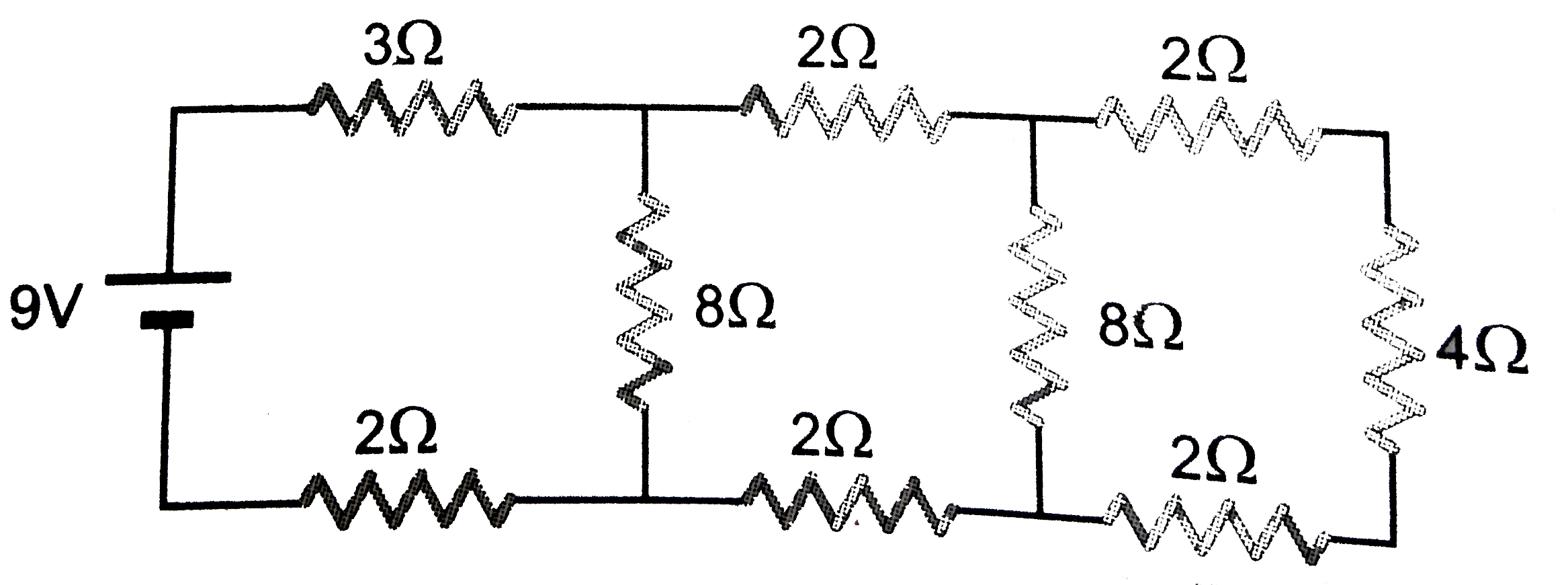
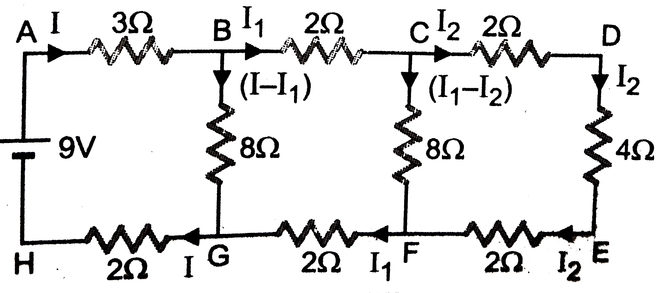
A
B
C
D
Text Solution
Verified by Experts
The correct Answer is:
Topper's Solved these Questions
CURRENT ELECTRICITY
PRADEEP|Exercise Jee (main and advance)|4 VideosCURRENT ELECTRICITY
PRADEEP|Exercise Interger Type|2 VideosCURRENT ELECTRICITY
PRADEEP|Exercise Value based|2 VideosCOMMUNICATION SYSTEMS
PRADEEP|Exercise MODEL TEST PAPER-2|9 VideosDUAL NATURE OF RADIATION AND MATTER
PRADEEP|Exercise Exercise|191 Videos
Similar Questions
Explore conceptually related problems
PRADEEP-CURRENT ELECTRICITY-Exercise
- In the circuit shown, the currect in the 1 Omega resistor
Text Solution
|
- In the R(1) = 10 Omega ,R(2) = 20 Omega, R(3) = 40 Omega R(4) = 80 Ome...
Text Solution
|
- In the circuit shown in the circuit through
Text Solution
|
- In the circuit E,F,G,Hare cell of emf 2,1,3and 1 Omega respectively .T...
Text Solution
|
- Shown a circuit with known resistance R,R(1) and R(2) neglect the resi...
Text Solution
|
- What would be the value of E so that the galvanometer G circuit shown ...
Text Solution
|
- In the circuit shown in figure the current flowing through 25 V cell i...
Text Solution
|
- A network of resistance cell and capacitor C(=2 mu F) is In steady sta...
Text Solution
|
- In the circuit shown in the figure, if potentail at point A is taken t...
Text Solution
|
- In the following circuit, the current through the resistor R (=2Omega)...
Text Solution
|
- A meter bridge is set up as shown, to determine an unknown resistance ...
Text Solution
|
- Seven resistances are connected The equivalent resistance of this net...
Text Solution
|
- Seven resistance are connected as shown in the firgure. The equivalent...
Text Solution
|
- In the circuit the resistance between A and C is
Text Solution
|
- The resistance in the two arms of the meter bridge are 5 Omega and R O...
Text Solution
|
- During an experiment with a metre bridge, the galvanometer shows a nul...
Text Solution
|
- A meter bridge is set up is as shown determine as unknown resistance X...
Text Solution
|
- A resistance of 2 Omega is connected across one gap of a meter bridge ...
Text Solution
|
- A uniform wire of resistance R is stretched uniform in a times R is t...
Text Solution
|
- A potentiometer wire of Length L and a resistance r are connected in s...
Text Solution
|

