Home
Class 12
PHYSICS
In the network shown in fig. , points A,...

In the network shown in fig. , points A, B, and C are at potentials of 70 V, 0, and 10V, respectively.

A

the potential of point D is `40V`

B

The current in the sections `AD,DB,DC` are in the ratio `1:2:1`

C

The current in the sections `AD,DB,DC` are in the ratio `1:2:3`

D

the network drawn a total power of `200 W`

Text Solution

Verified by Experts

The correct Answer is:
a,b,d

Refer Let `V` be the potential of point `D`

Then `70 - V = 10I_(1)`….(i)
and `V - 0 = 20 I_(2) or V = 20 I_(2)`….(ii)
and `V - 10 = 30(I_(1) - I_(2))`….(iii)
From (ii) and (iii),
`20 I_(2) - 10 = 30 I_(1) - 30I_(2)`
`30I_(2) - 50I_(2) = -10`....(v)
On solving we get
`I_(1) = 3A,I_(2) = 2A, (I_(1) - I_(2)) = 1A`
and `V = 40 V`
`:. ` Total power conssumed
`= (3)^(2) xx 10 + (2)^(2) xx 20 + (1)^(2) xx 30` M
`= 90 + 80 + 30 = 200 W`
Promotional Banner

Topper's Solved these Questions

  • CURRENT ELECTRICITY

    PRADEEP|Exercise Jee (main and advance)|4 Videos
  • CURRENT ELECTRICITY

    PRADEEP|Exercise Interger Type|2 Videos
  • CURRENT ELECTRICITY

    PRADEEP|Exercise Value based|2 Videos
  • COMMUNICATION SYSTEMS

    PRADEEP|Exercise MODEL TEST PAPER-2|9 Videos
  • DUAL NATURE OF RADIATION AND MATTER

    PRADEEP|Exercise Exercise|191 Videos

Similar Questions

Explore conceptually related problems

For the network shown in figure, points A, B and C are at potentials of 70 V, zero and 10 V respectively

In the network shown in fig. , the potential differene across A and B is

In the circuit given here, the points A,B and C are 70 V, zero, 10 V respectively . Then,

A hollow conducting sphere is placed in an electric field produced by a point charge placed at P as shown in figure. Let V_(A), V_(B), V_(C ) be the potentials at points A, B and C respectively. Then

Three uncharged capacitors of capacities C_(1),C_(2) and C_(3) are connected as shown in the figure to one another and the potentials V_(1),V_(2) and V_(3) respectively. Then the potential at O will be .

Three resistance are joined together to form a letter Y, as shown in figure. If the potentials of the terminals A, B and C are 6V, 3V and 2V respectively, then the potential of the point O will be

Three capacitors C_(1),C_(2) and C_(3) are connected as shown in, The potentials of P,Q , and R are V_(1),V_(2), and V_(3) , respectively. Find the potential V_(0) at the function O . .

Two points P and Q are maintained at the potentials of 10V and -4V, respectively. The work done in moving 100 electrons from P to Q is:

Four identical capacitors are connected in series with a 10 V battery as shown in the figure. The point N is earthed. The potentials of points A and B are

PRADEEP-CURRENT ELECTRICITY-Exercise
  1. A uniform wire of resistance R is slaped into a regular n-sided polygo...

    Text Solution

    |

  2. For the circuit

    Text Solution

    |

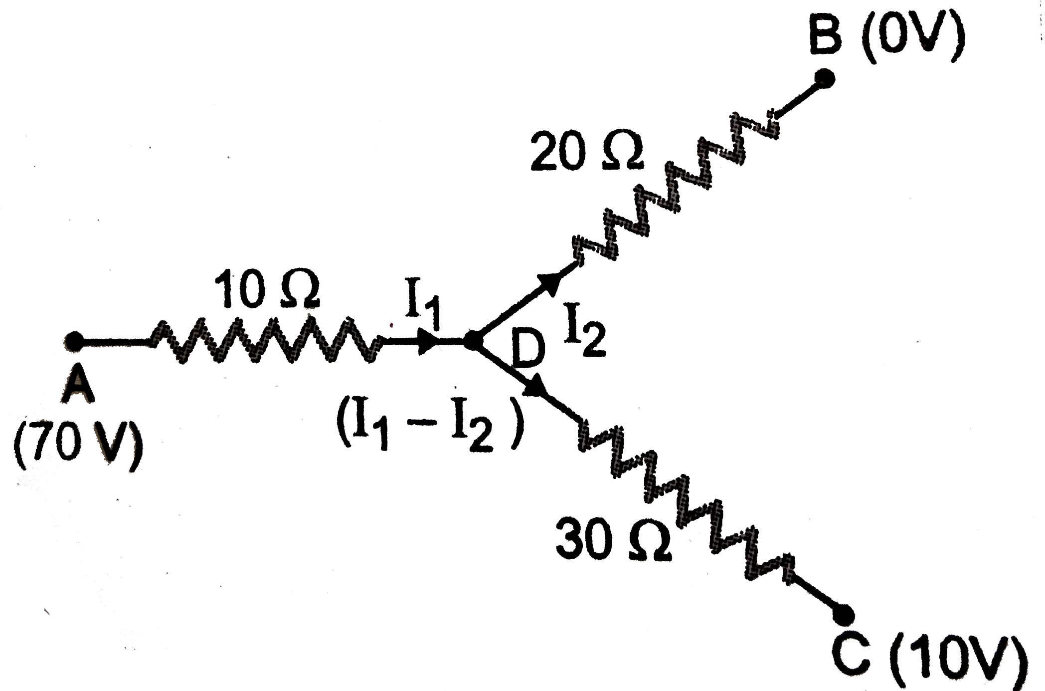
  3. In the network shown in fig. , points A, B, and C are at potentials of...

    Text Solution

    |

  4. For the resistance network shown in the figure, choose the correct opt...

    Text Solution

    |

  5. A current passes through a wire of nonuniform cross-section. Which of ...

    Text Solution

    |

  6. In the circuit elements given below, all individual resistors are iden...

    Text Solution

    |

  7. Two resistors having equal resistances are joined in series and a cur...

    Text Solution

    |

  8. A wire of length 12 cm resistance 12 Omega and of uniform area of cros...

    Text Solution

    |

  9. A wire of length 12 cm resistance 12 Omega and of uniform area of cros...

    Text Solution

    |

  10. A wire of length 12 cm resistance 12 Omega and of uniform area of cros...

    Text Solution

    |

  11. A uniform wire of resistance 9 Omega is cut into 3 equal parts. They a...

    Text Solution

    |

  12. The length of a potentiometer wire is l. A cell of emf E is balanced a...

    Text Solution

    |

  13. What should be the value of resistance R in the circuit shown in figur...

    Text Solution

    |

  14. Find the total linear momentum of the electrons in a conductor of leng...

    Text Solution

    |

  15. A battery of emf E and internal resistance r is connected is to extern...

    Text Solution

    |

  16. 32 cells each of emf 3V are connected in series and kept in a not Exte...

    Text Solution

    |

  17. When two identical batteries of internal resistance 1Omega each are co...

    Text Solution

    |

  18. Assertion: The bending of an insulated wire increase the resistance of...

    Text Solution

    |

  19. Assertion : The e.m.f. of the drivercell in the potentiometer experime...

    Text Solution

    |

  20. Assertion : A domestic electrical appliance working on a three pin con...

    Text Solution

    |